The html formatting and custom instructions have been disabled on this server. The same file with adapted formatting can be found here: https://farbeinf.de/static_html/render.html.
On the Screen – Simple!
It is simple to produce colour on the screen. The common web-browsers accept the representation of a colour by three numbers, which can take on values between 0 and 255, and thus are given by just one byte each. Three bytes, conveniently coded by hexadecimal numbers, for the luminosity of the red, green, and blue phosphors on the screen yield the desired mixed colour. The background-colour of this page is produced by the specification "background-color:#333333;" somewhere in the preamble of the html-document, #333333, in hexedecimal notation, stands for the three numbers 51, 51, and 51, the luminosities for red, green, and blue, respectively. The main headline got ist colour from color:#dd2244; – it is really simple.
Not so Simple?
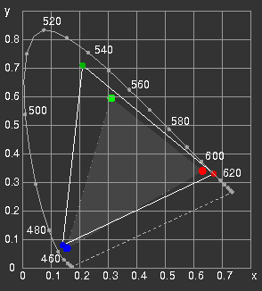
If, however, you want to know precisely which colour will result of a given setting, or when you want a very accurate reproduction of a given colour, it is not so simple. Take Green, for example, as given by 0, 255, 0. The following figure shows the CIE chromaticity diagram with two different sets of phosphors which are in use for cathode ray tubes (see e.g. Phosphors for cathode ray
tubes).
Figure 1: Two sets of CRT phosphors
The green phosphor could be Zn2SiO4:Mn
with colour coordinates x=0.208, y=0.704, or
ZnS:Cu,Au,Al with x=0.310, y=0.595.
Some monitors assume for White the colour temperature of 9300 Kelvin, many others use 6500 Kelvin; the technical descriptions seldom tell which phosphors are used.
The smaller, grey triangle in fig. 1 is the SMPTE-C colour gamut (SMPTE: Society of Motion Picture
and Television Engineers), so to say standard for TV screens (cathode ray tubes) in America; the EBU (European Broadcasting Union) has chosen slightly different values as the colour primaries of PAL and SECAM TV.
SMPTE-C
EBU (PAL, SECAM)
Red
Green
Blue
x
0.63
0.31
0.155
y
0.34
0.595
0.07
Red
Green
Blue
x
0.64
0.29
0.15
y
0.33
0.60
0.06
The White Point is D65 in both cases, with xw=0.312713, yw=0.329016.
It is not only the chromaticity coordinates which are decisive in the choice of phosphors. Yield, afterglow and stability are also important criteria.
There is a variety of phosphors for CRTs, flat TFT screens produce colours with colour filters.
Thus one has to keep in mind: the colour produced by specifying three numbers for the red, green, and blue intensities is device dependent.
Colour Profiles and Gamuts
If images shall be reproduced equally well by different devices, instead of specific RGB-numbers a set of device-independent colour coordinates must be used, as supplied by the CIE-XYZ colour space or spaces derived from it, which have been dealt with in the section on colorimetry. The prescription how to convert these coordinates to the device-RGB or CMYK values is called the colour profile of the screen or printer or ...
As the colour signal can be transformed prior to rendition on the screen, a standard colour space has been proposed for the World Wide Web, sRGB
which has been widely accepted. Independently of the phosphors actually used, modern screens allow to choose the sRGB colour space among the settings. As most digital cameras use the sRGB space, and since the differences between sRGB, SMPTE-C and EBU standards are small, it is recommended to assume the sRGB colour space when producing pictures for presentation in the internet, as well as in most other cases too.
Modern scanners and ink-jet printers, photo printers in particular, are using the sRGB colour profile as default and offer the possibility to use other profiles.
The Adobe RGB(1998) colour space has been designed for high quality printing. The CMYK gamut contains blue and blue-green colours of higher saturation than contained in the sRGB colour space. Even if the Adobe RGB (1998) can not be reproduced correctly on the computer screen, it may make sense to use this space when producing pictures which shall be rendered in print (selecting the appropriate parameters on the printer).
sRGB
Adobe RGB (1998)
Red
Green
Blue
x
0.64
0.30
0.15
y
0.33
0.60
0.06
Red
Green
Blue
x
0.64
0.21
0.15
y
0.33
0.71
0.06
The White Point for both is D65 (as above).
Fortunately it is not very often necessary to exactly specify the colours on the screen. Our visual system adapts readily to changes of the illumination, and this ability lets us tolerate overall shifts of hue in the pictures.
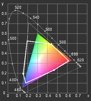
By additive mixing, only colours within the triangle spanned by the primaries can be obtained.
Figure 2:
The CIE-x-y-diagram with spectral locus, purple line annd comparison of different colour gamuts: sRGB (coloured), Adobe-RGB (1998) (grey outlined triangle) and the gamut of four-colour printing with standardised printing inks (after DIN 16539) (white-outlined hexagon).
From figure 2 one might get the impression that most colours can not be reproduced by the sRGB primaries. However, the colours outside the gamut are only very seldom seen in nature. Highly saturated purple and blue-green colours are missing also in TV. But have you ever been annoyed by that?
Brightness and Colour Steps: Gamma Correction
With a limited number of steps available, it is best to choose equidistant steps. Steps which are perceptually equidistant, not with respect to the physical energy flux.
In a cathode ray tube, the current is controlled by the voltage. The brightness is proportional to the current, but the current depends nonlinearly on the voltage, and is described in good approximation by a power law:
I/I0=(V/V0)γ
The exponent, the notorious γ (Gamma), typically is in the range between 2 and 3.
Experience shows that, with a γ of 2.2, a linear increase of the voltage leads to a perceptually linear increase of the brightness. (The optimal value of γ depends on the general illumination level; in a dark room, higher γ is better.)
Thus, in the early days of television, the physical properties of CRTs were quite convenient, but nowadays, the necessary "gamma-correction" is no longer left to the inherent properties of rendering devices, instead, a built-in look-up table (LUT) provides the desired functional dependence.
Let L be the perceptual and Y the colorimetric brightness (luminance).
Both are supposed to attain the value 1 for White, 0 for Black. According to the preceding considerations, we have
Y = Lγ.(1)
For technical reasons, the above formula is slightly modified:
Y = [(L + a)/(1 + a)]γ,(2)
where a is a small positive constant. For L = 0 this yields a small positive value of Y; this is corrected by assuming a linear dependence for very small luminosities:
Y = kL ,(3)
and adjusting the constant k for a smooth transition.
The inverse relation is
L = (1+a)Y (1/γ) – a(4)
(for not too small values of Y.)
The sRGB colour profile (proposed by M.
Stokes, M. Anderson, S. Chandrasekhar, R. Motta 1996) uses γ = 2.4, a = 0.055, corresponding to an "effective" γ of 2.2; the Adobe RGB (1998) profile uses γ = 563/256 (approximating 2.2), and a = 0.
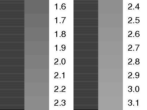
Figure 3 can be used to determine the gamma of one's screen.
The picture is to be viewed from some distance so that the striped parts look uniformly grey. On the right of the grey field which has the same brightness as the "striped" grey the corresponding γ is given.
The illustrations here are correct for γ = 2.2.
Figure 3: Gamma test, using Y = Lγ
Rendering on the Screen
RGB Values
Independently of the way how the colour signal is coded for transmission, in the final step when a pixel is reproduced, the intensities of the three primaries Red, Green, and Blue must be controlled. Even if a graphics program or the page-description programming language PostScript offers different possibilities to determine colours: it is always the thee numbers R, G, and B determining the currents of the three electron beams (or the transparencies of the red, green, and blue parts of the pixel, respectively).
The maximum brightnesses of the three primaries are adjusted so that all three together yield "White". These intensities are assigned the numbers 255 (or #ff in hexadecimal notation). It is required that, if R = G = B, neutral grey results. This means that the gamma-correction must be the same for all three colours.
In the following, the maximum luminosities are normalized to 1 (as it is done in the PostScript language). The corresponding numbers are called R', G', B', they are related to the colorimetric intensities R, G, B by the following equations:
R = [(R' + a)/(1 + a)]γ, G = [(G' + a)/(1 + a)]γ,(5) B = [(B' + a)/(1 + a)]γ,
with constants γ and a defined above.
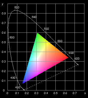
If the chromaticity coordinates of the primaries are known, from R, G, B the CIE coordinates X, Y, Z and all quantities derived therefrom can be obtained, and vice versa from X, Y, Z one can get R, G, B and R', G', B'. Thus, at least on the screen, very faithful rendering of colours is possible – if the colours are within the gamut. As an illustration the 1931-CIE xy-diagram is given here (Figure 4) together with the PostScript source code
.
Figure 4: The 1931 CIE-xy-diagram as an example for the calculation of colours. The sRGB colour space has been assumed.
There are many similar pictures to be found in the internet. Some of them agree with this figure (e.g. that in the
Wikipedia), others show considerable deviations due to detectable programming errors (the White Point is not where it should be). This is one of the reasons to give the source code here.
HSB and HSL
As alternatives to the specification of colour by the R',G',B' values, in drawing and graphical software colours may also be given by hue H, saturation S, and brightness (value) V or lightness L, which is considered to be much more intuitive. The gamut is, however, exactly the device RGB space. Taking the parameters H, S, and V as cylindrical coordinates, a colour solisd in the shape of a cylinder results.
Figure 5: Colour wheel showing the hue H for saturated (S=100%) colours of maximum brightness (V=100%). The primaries R, G, B are placed at 0, 120, and 240 degrees, the binary mixtures (subtractive primaries) Y, C, and M at 60, 180, and 300 degrees, respectively. In the six intervals between Red and Yellow, Yellow and Green, etc., the R', G', and B' values are linearly interpolated.
In the HSB (also called HSV) model, the colours seen in Figure 5 are assigned brightness 100%. For reduced brightness, the R', G', B' values are multiplied by V, for reduced saturation, the values are linearly interpolated between the circumference and the grey axis. Figure 6 shows a section as an example.
Figure 6: Section through the HSB cylinder from H=210 to H=30. In the rows, saturation S changes by 20% of the maximum value from one field to the next; in the columns the steps of the value V are 10%. (For magnification click on the image!)
In the HSL-model, the colours shown in figure 5 are assigned the lightness L=50%. Lightness L=100% is white and L=0% is black for all values of H and S. A representative section of this cylinder is shown in figure 7.
Figure 7: Section through the HSL cylinder from H=240 to H=60. The lightness is increased in steps of 10% from bottom to top, the saturation changes are 20% in the horizontal direction. Note the discontinuity in the perceived step size at L=50%.
For further image processing, the H, S, and V or L values are first converted to R', G', and B'; the new parameters only offer a more intuitive access.
Printing
Cyan, Magenta, Yellow, and Key (blacK)
When printing on white paper, the intensity of the remitted "red" light is controlled by the blue-green, "Cyan" ink, the yellow ink reduces the amount of remitted Blue, while Green is controlled by purple ink (Magenta).
Yellow, Cyan, and Magenta printed on top of each other do not produce good black; therefore, for better brilliance, the fourth colour Black is used (called Key in printing technology). On the Screen, this fourth "colour" is not necessary.
Using the CMYK (Cyan-Magenta-Yellow-blacK) colour space on the screen, one may always use K = 0, and the transition from R', G', B' to C, M, Y is simply
C = 1 – R', M = 1 – G', (6) Y = 1 – B'.
However, the gamut obtainable with printing inks is different from that of the screen; moreover, the printing inks only approximate the CMY ideal colours, technical peculiarities must be considered, so that the transformation formulas which lead to the best results may be considerably more complicated.
Formerly, three- and four-colour printing was only possible for industrial printing plants. Digital image processing has revolutionised its workflow. Digital cameras, scanners, inkjet printers, and personal computers with powerful software are acessible for most of us.
Figure 8: a light grey area in three-colour printing under the microscope.
In the case of TV or computer monitor screens, the colour profile, i.e. the transformetion between trichromatic coordinates X,Y,Z (or others derived from these) and device- specific values of R', G', B' may be given by simple formulas. The corresponding task for four-colour printing is not so simple.
In the above figure of a light grey area, eight different colours van be seen: the White of the paper, the three printing inks cyan (C), magenta (M), and yellow (Y); areas covered by two of these inks are red, green, and blue; and areac covered by all three inks are black (or dark grey). The uniform colour impression results when the raster dots are not resolved, by averaging.
Let us consider the set of equations (6):
C = 1 – R', M = 1 – G', Y = 1 – B'.
The numbers C, M, Y which can assume values from 0 to 1, correspond th the fraction of the paper surface covered by the respective ink; C=0.4 means that the cyan ink covers 40% of the paper and 60% are free of that ink. Strictly speaking, a gamma-correction should be performed, but, as we can see in figure 2, the coordinates of the green colour obtained from printing with cyan and yellow ink, are very different from those of the green primary of the screen, and in addition, also the relative brightnesses are very different. Therefore, the C, M, Y values calculated from R', G', B' are only crude approximations and of no practical use.
Therefore, in the colour profile, a look-up-table (LUT) is used to correlate the colour coordinates with the printers' CMYK values. This is obtained by printing a test pattern which is then measured under standard conditions. By this, the properties of different kinds of paper can also be accounted for, and the printer drivers are equipped with colour profiles for all kinds of paper to be used.
For in-gamut-colours, exact colour fidelity can be achieved in this way – assuming standard viewing conditions. But what about the colours outside of the reproducible gamut?
Following a proposal of the ICC (International Color Consortium), this is determined through the choice of the rendering intent (see the specifications).
Four different intents are specified:
Perceptual (photo-realistic): All colours are mapped to points within the destination gamut. This means that colours are de-saturated, linearly or nonlinearly, in order to yield an overall pleasing appearance and to avoid the loss of distinction between similar colours outside of the gamut.
Relative colorimetric: Colours outside of the gamut are projected onto the border. The white point is assumed to be the colour of the paper.
Saturation: colours are moved towards the gamut's boundary. Useful if vivid colours are more important than the exact hue, as for business graphics (charts, graphs etc.).
Absolute colorimetric: similar to the relative colorimetric intent, but the white point is that of D50 illumination. This is useful for calibration purposes.
Colour Management
To the user, the output colour profiles contained in the drivers of inkjet or laser printers are accessible by choosing the paper quality, the rendering intent, and perhaps correcting a colour fault, while the input profile may be set automatically by the operating system or manually by the user.
Professional digital cameras and scanners offer a choice of different output profiles. Depending on the intended purpose it may make sense to switch between different profiles.
The colour measurement which is performed by the camera or the scanner for every pixel, covers the full gamut of all visible colours if the sensitivity curves are properly chosen.
Consider the scanner, for example. In its configuration menu, there are typically two colour profiles: one for the input or source, namely the scanner itself, and one for the output (target). The source profile contains all data necessary to convert the measured red, green, and blue components of a pixel to coordinates in a device independent colour space, say CIE-XYZ or CIE-Lab. The target profile can already account for the designated use of the scanned image. The default setting is today (2010) sRGB; the image file can be shown on most computer- or tv-screens without any colour conversion.
If, however, the image is to be printed and, in addition, contains saturated green and blue-green, the choice of the Adobe-RGB(1998)-Profile is recommended. Of course, also the printer then has to be told to use this profile.
Technological progress makes screens available with considerably larger gamut than sRGB. To make use of their capabilities, larger gamuts will increasingly be used for images. The mixture of images defined in different spaces is then unavoidable. To achieve colour fidelity, it is advisable to embed the necessary colour profiles into the images. The software, browsers and printer drivers in particular, should then be able to respect the embedded profiles of individual pictures.
This can be checked by the three pictures below:
If image in the middle is identical to the left one, then your browser honours embedded profiles; if it is identical to the right one it does not.
Figure 9: sRGB
Figure 10: wideGamut with embedded profile
Figure 11: wideGamut without embedded profile
Things are changing.
Today (April 2010) most of the actual browsers ignore colour management. Image viewing software should offer the possibility in the settings to enable colour management.
The format of colour profiles is specified exactly in the specifications published by the ICC, as well as the prescription how to include the .icc (or .icm) files into the different image files. This is not particularly simple, but, thanksworthy, helpful tools may be found in the internet. I have used ExifTool by Phil Harvey (description and download) to tag the images above. The necessary profiles (.icc-files) can be downloaded as well (e.g. from here or here), if they are not already on the hard disk.
Colour Fidelity
In the figures where computed colours are shown, I have explicitely performed the transformation of the CIE XYZ coordinates to the sRGB coordinates. This transformation could also be left to PostScript which allows to use the CIE-XYZ space, among others.
It is not infrequent that some of the computed (or measured) colours are outside of the device gamut (which I have assumed to be sRGB), so that one or two of the values of R, G, B are larger than 1 or smaller than 0 (example: the soap film). In PostScript, these values are replaced by 1 or 0, respectively, without warning or error message. If one wants to keep control of this, one has to compute R, G and B to see whether the boundaries are exceeded.
An example: computed colours of a tapered thin film, using the sRGB space, looking quite nice on the screen –
Figure 12
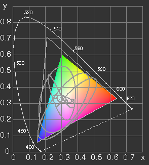
the printed output on a photo printer is, however, not satisfactory. If the computation is performed using the Adobe RGB (1998) space, after setting the printer's parameters to this space, the printed output is really good, exhibiting more saturated blue and blue-green shades than seen on the screen. Figure 13 shows the loci of these colours, the coloured sRGB gamut and the outline of the Adobe RGB gamut.
The calculation is shown here with all details.
Figure 13
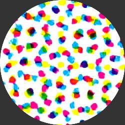
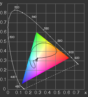
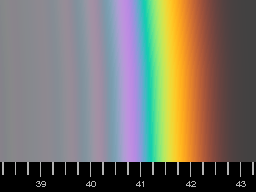
One more example: computed colours of a rainbow produced by drops of uniform size with 0.7 mm diameter. As a rainbow is never seen with a black background, here a dark grey background has been assumed. (This would already be produced by the light reflected from the front surface of the drops.)
Figure 14 (left): loci of the rainbow colours, assuming a background of luminance Y = 0.05 and uniform droplet size of 0.7 mm diameter.
Figure 15 (below): On a sRGB screen the computed rainbow colours should be rendered accurately.
As is seen from figure 14, all the rainbow colours are within the sRGB gamut, so in this case there would be no advantage in choosing the Adobe RGB(1998) colour space for printing.
)
)
)
)
)
