Two-beam interference: thin films, birefringence and polarisation …
The html formatting and custom instructions have been disabled on this server. The same file with adapted formatting can be found here: https://farbeinf.de/static_html/twobeams.html.
Thin films
Transparent thin films often show vivid colours. This can be studied most easily and clearly on soap films or bubbles.
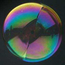
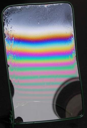
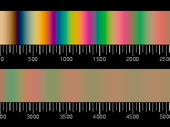
Below: Left: Tapered soap film in an inclined frame, reflecting light from the overcast sky. Due to gravity, the film is very thin on top; its thickness is increasing downwards.
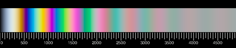
Right: The result of a computation. The scale under the coloured strip gives the optical path difference of the two interfering rays in nm (nanometers).
|
 |
 | |
The sequence of colours is very characteristic. The phenomenon is easy to explain and easy to calculate. A small fraction of the incoming light wave is reflected by the front side of the film whereby the sign of the electric field is inverted, an other, approximately equal part is reflected by the back side without change of sign, so the superposition of both reflected waves is given by the difference of two waves which have travelled different paths. The result depends on the difference of the optical path lengths which can be easily found out from a simple sketch. The geometrical path lengths have to be multiplied with the refractive index of the medium.
|
If the film is very thin, the path difference being much smaller than the length of the shortest visible lightwaves and thus approximately zero, then the superposition of both reflected waves (the difference!) is very small for all wavelengths, there is almost no light reflected. With increasing path difference, the intensity goes up for all wavelengths, and after passing a maximum it decreases again, which happens first for the shortest wavelengths. The soap film looks yellowish, then reddish, and when the wavelengths of yellow-green light are cancelled it looks very dark, because the eye is most sensitive to yellowish green. ...
The relative intensity of the reflected light is easily calculated; using the CIE spectral functions xλ, yλ, and zλ one obtains the tristimulus values of the reflected light and eventually the coordinates R, G, B for its rendering on the screen. The calculation is given here with detailed comments as an example for all similar calculations, and with a FORTRAN sample code.
The agreement of both pictures is satisfactory, though there are subtle discrepancies.
Which of the pictures agrees better with reality?
To answer this question, an experiment is needed.
The photograph has been taken with a digital camera. Photographic film would exhibit much larger discrepancies.
This can be seen here.
In fact, the soap film is a very hard test for photographic colour rendering.
Two beams of light which have followed slightly different paths are interfering; this is an example of two-beam interference.
 | |
The tapered soap film with a white background.
The photograph above shows a soap film in front of a dark background. All the light seen has been reflected on it. In transmission, the interference effect is much less conspicuous, nevertheless "Newton rings" are somtimes a nuisance in slides between glasses. The reflected colours are missing in transmitted light, therefore the complementary colours are seen. As only a small fraction of the incident light is reflected, these colours are only faint. |
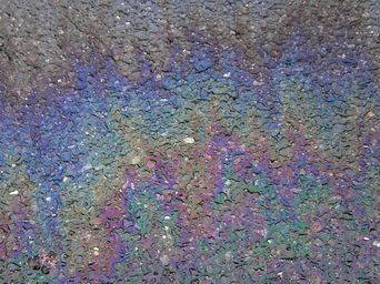
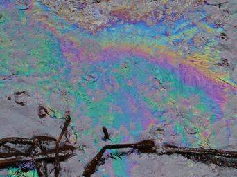
A thin film of mineral oil floating on water shows similar colours, and in fact, the physics is also very similar. The refractive index of oil is larger than that of water, therefore the reflection on the back side occurs without change of sign as before. The difference of the amplitudes of the two interfering waves has no big effect on the result. Bacteria can also form films which have similar optical properties as oil films.
 |
 |
|
Oil drops spread to thin films on wet pavement. |
A film of bacteria on water at a muddy spot near the edge of a pond. |
|
 |
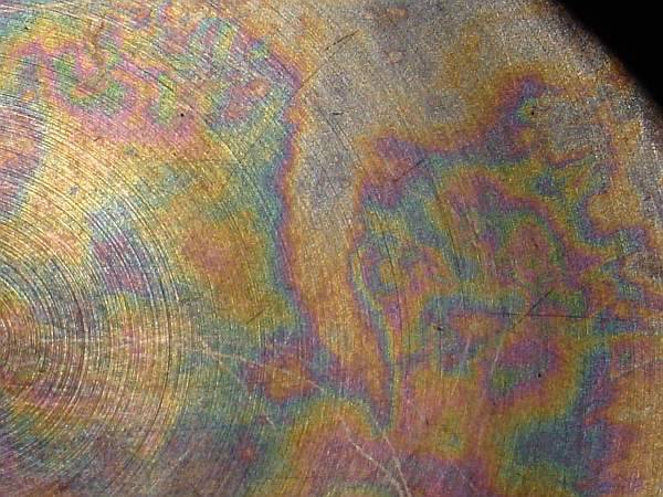 |
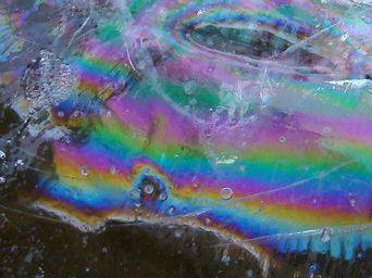
| Ice on a pond with air-filled fissures produced with a hammer (magnification approximately 2x) | Stainless steel bottom of a cooking pot. After cooking meat, vegetables etc., sometimes a thin film, probably of proteins, adheres to the metal and resists washing |
It does not matter whether the reflecting thin layer has a bigger index of refraction than the surrounding medium or a smaller one – the colours are the same.
The physics is more complicated in the case when the film is on a metal surface, but the colours are quite similar. An expression for the reflectivity of a metal covered by a transparent film is given here. In fact, stainless steel is covered by a very thin passivation layer of chromium(III)oxide, too thin to produce noticeable visible effects, and I guess that it does not become much thicker when meat is cooked in the pot, but rather that another transparent layer forms.
Whereas the colours of thin films can be seen quite often, it is less well known that the same colours may originate from an other mechanisn, namely
Polarisation and birefringence
Anisotropic materials, if transparent, are generally birefringent. We consider here the simpler case that there is only one axis of anisotropy (symmetry axis, optical axis). If light enters such a material, it is split into two linearly polarised rays. The electrical field of the ordinary ray is orthogonal to the optical axis, that of the extraordinary is in the plane spanned by the optical axis and the direction of propagation.
These two rays encounter different refractive indexes. In most cases this is not conspicuous, as the eye is not sensitive to the polarisation of the light.
If, however, polarising filters are in the light path before and after the birefringent medium, the situation is different.
The first filter secures that the two rays enter the sample with the same phase. Because of the different refractive indexes, their optical path lengths through the material are different and a phase difference arises. Only a part of each ray passes the second polarisation filter. Depending on the phase difference, these parts may now interfere constructively or destructively. Extinction occurs for crossed polarisers if the path difference is a multiple of λ. Vivid colours result from this wavelength-dependence of extinction and amplification.
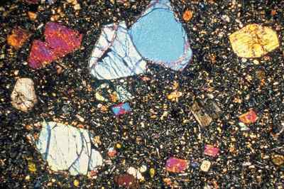
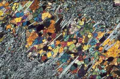
Thus, in the ivestigation of thin sections of rocks between crossed polarisers again two-beam interference is observed: the possible colours are the same as those of soap bubbles; from the colour one can obtain the optical path difference of the two interfering beams (ordinary and extraordinary rays in the birefringent medium) and can draw conclusions on the mineral composition of the sample. Below two images of thin ground sections of rock under the polarisation microscope are shown.
 | |
|
Basalt with olivine and pyroxene.
width of the image: 3.3 mm.
| | Olivine,
width of the image: 3 mm.
|
Pictures: courtesy of professor Dr. W. Johannes (Leibniz University Hannover).
One expects that birefringent substances like crystals or acrylic glass with inner tensions etc. will show colours between polarisers. But incidentally, such colours appear without any special devices as a surprise.
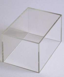
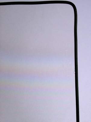
Left: A small box made of acrylic glass, placed on a sheet of paper, at daylight – there are no colours.
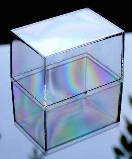
Right: In the light of the blue sky, the same box appears faintly coloured, its mirror image in the glass plate beneath is really colourful.
Light from the blue sky is partially polarised – this acts as substitute for the first polariser, light reflected from glass or other transparent glossy surfaces is partially polarised too and substitutes the second filter. The box was manufactured by injection molding and is birefringent due to inner tensions.
In photography, polarisation filters are used to reduce reflections of glossy surfaces like glass or water and to intensify the colour of the sky. This may occasionally introduce unexpected colours like those shown in the picture below:
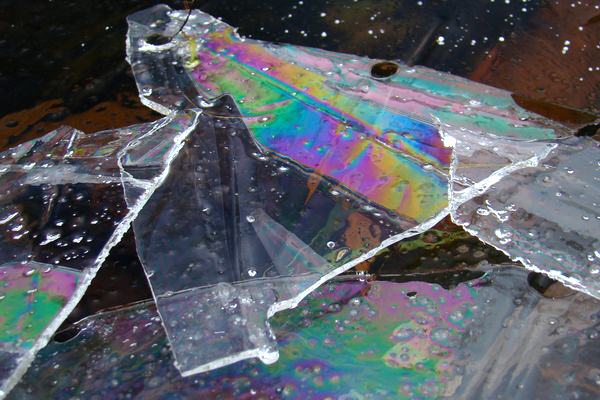
Birefringence of ice: pieces of the thin ice crust of a pond stacked on top of each other with air-filled gaps between them, photographed with a polarising filter.
Without the filter, the bright (grey) sky would be reflected by the flat pieces of ice. But the reflection from the upper surface is suppressed by the filter, and the polarised reflected light from the lower surfaces passes the birefringent ice. Depending on the orientation of the optical axes of the large single crystals, this may or may not result in fancy colours.
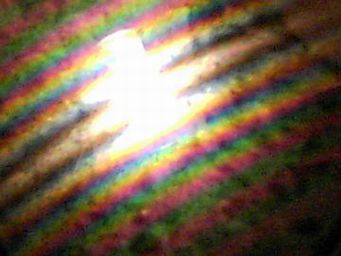
Three more images: (1), (2), (3). Number 1 has been taken under the same conditions as the image above, numbers 2 and 3: a piece if ice is held before the reflection of the sun in the pond and viewed through a polarising filter.
|
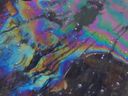
As thin fissures in ice may cause the same colours (see thumbnail to the right), those caused by birefringence are prone to be misinterpreted. The photograph has been taken without a polarising filter!
|  |
| One more example of colours due to birefringence is treated in the special section Kaleidoscope Calcite | 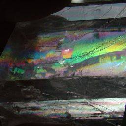 |
Quételet rings or stripes
These interference colours are rarely seen. Without the
photographs by Eva Seidenfaden I would not have looked for them. The geometrical arrangement to observe them must be such that the mirror images of the observer's eye and that of the light source are close to each other.
Left: Quételet stripes on a mirror dusted with starch powder in the light of a halogen lamp.
Right: Computed colour sequence for this case of two-beam interference, assuming a colour temperature of 3500 K for the lamp. The scale gives the optical path length difference.
In this case, the two interfering beams are: light which is scattered by a dust particle, then enters the glass, is reflected at the (silvery) back side and finally reaches the observer, and light, which first enters the glass, is reflected at the back side and is afterwards scattered to the observer by the grain of dust.
Along a line which apparently passes the mirror image of the lamp, the paths of both beams are equal, and there is the maximum intensity. If the light source and the observer's eye have the same distance to the mirror, this line is straight. Otherwise it is a part of a circle. If the lamp is closer to the mirror than the eye, it bends away from the mirror image of the observer, if the lamp is farther it is concave to it. A simple calculation shows that, in the case of a plane parallel mirror, the stripes are concentric circles.
Here is a more detailed description.
An experimental setup is given by H.J. Schlichting with a rare example of an outdoor observation.
Proceed to multiple-beam interference,
back to diffraction
or back to the index page "the origins of colour"
Legal Information Data Privacy
)
)
)
)
)
)