)
)
)
Quetelet rings may be not very rare, but until now I have only seen artificially produced ones. Impressive examples due to dust particles or algae on the surface of a pond or puddle may be found in the web [1], [2],[3], [4].
Recently Aleksandr Berdnikov uploaded three photographs of a dusty mirror which show this phenomenon very clearly:
The images (source: Wikimedia Commons [A], [B], [C]) have been taken with lhe light source closer to the mirror than the camera (about half as far, left image), with the flashlight twice as far as the camera (middle), and with camera and light approximately at the same distance (right).
Aleksandr in his comments to the images describes the relative positions of the flashlight to the camera; but this can be deduced from the images, if only the relative distances are known. In the right picture, the mirror images of the light source and the camera are visible, therefore the arrangement is clear. The other two photos show only the flashlight mirrored. But the dark area in the lower right corner of the first picture must be the back of the light, thus it is to the right and lower than the camera, while in the second picture there certainly it is the shadow of the camera which obscures part of the lower right, which means that the light is to the left and higher up. There are some reflections of the surroundings in this shadow and below. (Click on the pictures to enlarge!)
As seen on the photographs, the rings are circular, but unlike coronas or aureoles they are not centred around the light source.
)
)
)
I first deal with the case (which I haven't yet seen) of algae like Chromulina rosanoffii over a calm water surface. As shown by Marko Riikonen [4] “this unique sort of alga separates itself from the water surface by forming a stalk on top of which it rests”.
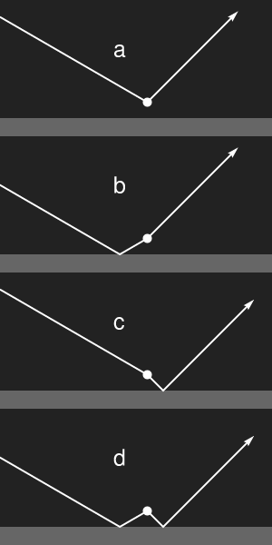
The colours are due to the interference of light rays coming from the same point of the source and arriving at the same point of the retina (or the camera's sensor), but having travelled different paths. The two interfering beams are: light, which is reflected at the water surface and is afterwards scattered to the observer by the particle (an alga), the black line in the neighbouting sketch, and light which first is scattered by a particle, then is reflected by the water surface and finally reaches the observer (white line).
The sketch to the right is not to scale, actually the particle (white circle) and its mirror image (light grey circle) are so close together that they cannot be resolved by the eye (or camera).
Knowing that the rings are concentric circles (I shall show this later), it is not difficult to find the position of the centre. Consider the brightest circle which goes through the mirror image of the sun, which is the locus of all points where the two paths have the same length. Another easily to locate point on this circle is the antisolar point in the shadow of one's head. The centre of the rings is just halfway between the antisolar point and the image of the sun, and this is just under the feet of the observer, the nadir.
This is not the case if the light source is close, comparable with the distance of the observer from the mirror. Instead of the antisolar point now the point has to be considered which is just hidden by the lamp (B in the adjacent sketch) or where the shadow of the observer's eye would be (B in the rightmost sketch). If produced by dust on a mirror, the rings are only seen if the illumination angle and viewing angle (as measured from the normal) are small. The pair of sketches to the right illustrates how to find the centre of the rings in this case, and they also illustrate that the rings on the mirror are not changed when the positions of observer and lamp are exchanged.
The three photos below have been taken with a small circular mirror with 11 cm diameter. For the left and middle one, a small incandescent lamp was positioned approximately 5 m far from it, and the camera at about half that distance. These two images differ only in focusing: the rings get more pronounced if the light source is in focus, not the grains on the glass.
The third photograph below has been taken with the camera at 2.5 m and the lamp at 80 cm effective distance. A glass plate has been used to reflect its light to the mirror, therefore “point B” is not obscured by the lamp's case.
)
)
)
To show that the coloured rings are circular, I first treat the simpler case … READ MORE
Optical effects on spider webs have already been treated here [1], [2]. There, the main focus was on the colours seen on the sticky threads of orb webs lit from behind. The non-sticky strands show less conspicuous colours to the eye, but recently I saw a series of surprisingly candy-striped out-of-focus highlights in the blog “The Natural History of Bodega Head” by Jackie Sones [3a, b, c, d, e, f] , which puzzled me. Here are two examples (shown with permission):
)
)
Why are many of the glints cigar-shaped? Shouldn't one expect that the blurred image of the gloss is everywhere as wide as that of the strand so that the shape would be more or less rectangular?
Fortunately a cellar spider provided the possibility to investigate this. Cigar shaped striped highlights could be obtained, but the results seemingly depend on the camera. The above pictures have been taken with a SLR camera with a 22.5 × 15 mm sensor; my camera's sensor measures 6 × 4.5 mm.
)
)
With bare eyes this could not be seen because one involuntarily focuses on the spot where one looks, and then most of the colours vanish. But even if one succeeds to focus on the far background with a glistening silk strand nearby, the colours will not be as beautiful as in a photograph. With the camera arbitrary defocussing is easy, and moreover, details of a high resolution image can be enlarged. The larger the sensor of a digital camera, and the larger the aperture, the more impressive are the results.
When focused to infinity, so to say to the sun's one-dimensional mirror image, the highlights are only thin stripes orthogonal to the threads. The width of the coloured stripes is the apparent diameter of the sun, their length is the apparent breadth of the out-of-focus strands (which are not seen in the right picture except for their glints). The closer the strands, the longer the stripes. If, however, the strand is focussed at, the (one-dimensional) image of the sun gets blurred and the gloss is seen on a longer stretch which is given by the apparent diameter of the blurred sun.
The colours are due to the fact that the surfaces of the silk strands are not smooth, but slightly wrinkled. If out of focus, light arriving at one point of the sensor comes from nearby points of the strand and has travelled different path lengths because of the wrinkles. Interference can result in extinction of parts of the spectrum and enhancement of other parts. This is perceived as colour.
But what is the reason for the peculiar shapeof the highlights? Read more …
After having written about the dewed windowpane, I did not see again such a colourful aureole. But it is possible to see a quite similar one when breathing on the window glass while looking at a distant street lamp. In this case, one can to some extent vary the sizes of the droplets and their distances. The following images have been obtained in that way.
)
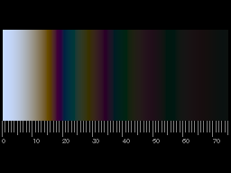
As only a small part of a window can be breathed at, the produced mist is not uniform. Therefore, the diffraction image is not easily interpreted. Towards the rim of the misted area, the droplets get smaller and their distances increase. In the adjacent image the outermost region is grey, which means that the scattered light is white, though dim. The droplets are so small that the product of scattering angle times droplet radius corresponds to the central region of the diffraction image of a small disc. The small picture below shows the computed colours for diffraction by a circular black disc; the scale gives the product of deflection angle (in degrees) and radius (in micrometers). (The similarity of the diffraction patterns of small drops and black discs has been demonstrated elsewhere. More on that can be found in the section on diffraction.)
Towards the centre of the misted area, the sizes of the droplets increase, and though the scattering angle gets smaller, the product of angle times radius at first increases and the colour becomes straw yellow, brownish, then dark purple and dark green. Still closer to the centre, one might expect the colour sequence to be reversed, as the product mentioned decreases again, but now the density of the droplets is so high that the interference effects due to short-range correlations take over, and the previous description is valid. For the smallest scattering angles, there is almost complete destructive interference, the immediate surrounding of the lamp, i.e. the centre of the aureole is dark, and then follows a ringed “spectrum”, blue, then white, then red. In the following, only this central region is dealt with.
)
It is remarkable how the diffraction image changes when the breathing on the glass is continued so that the density of the mist is slowly increased, or when one first looks throught the outer region of the mist and then moves towards the centre. At first, there is a large dark central region surrounded by greenish grey, then yellow and red. Then, almost suddenly, the radii of the rings decrease and also their colours change.
This can be seen in the image to the right. The photograph has been taken looking not through the centre of the misted region, but to the left of it, so that there is more moisture to the right of the image of the lamp than on the left side. If the droplets would be denser to the right, the radius of, say, the red ring would be larger there than on the other side – but it is smaller! The distances between neighbouring droplets thus must be larger there, and this is only possible if small droplets have joined to form larger ones. The spectrum now goes from dark blue through cyan, almost no white to a reddish seam. (The images may be enlarged by clicking.)
The following four pictures show the continuation of this process. More and more droplets coalesce to form larger and larger ones, and correspondingly the dark region around the lamp shrinks, and so do the coloured rings around it.
)
)
)
)
The photos have been taken in December. Some days ago, now in August, I tried to document this in a video – but the colours were only pale and the rings much less clear. Apparently the dew droplets on the glass are less uniform at higher temperatures, probably due to evaporation. I will try again next winter.
View from the hotel window on the parking area at the airport. Through the thin curtain the highlights – reflections of the sun on the glossy car bodys, windscreens or back windows – are seen split into diffraction patterns. The image to the right shows an enlarged detail.
)
)
Below: to the left a close-up of the curtain, image width 12 mm. To the right an older photo, likewise taken through an hotel window's curtain. The thin fabric decorates the headlights with diffraction patterns which, however, are less distinct because of the sizes of the lights.
)
)
The following images have been taken in February 2017 in Äkäslompolo, Finland, Lapland (67° 36' 26" N, 24° 09' 33" E).
)
)
)
)
While in the visual impression of the images in the upper row a faint yellowish-greenish hue could be sensed (or guessed), the colours seen in the lower row (except those of the bright artificial lights) were not visible for the eyes, only shades of grey could be perceived.
The white point has been set to the same value, namely 6500K, in all four cases, see the discussion given earlier. For more details on the aurora, see the article on atomic spectra.
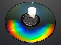
The case of a CD is lying on the table and mirrors the lamp. But there are also rainbow colours from diffraction!
)
)
)
A similar effect with transmitted light has already been presented here, and it is assumed that the reason is the same: “In the process of injection moulding, it may happen that the plastics in touch with the mould cools, gets sticky, and is overtaken by the warmer inner layer. When this touches the mould, the process repeats, repeats again and again, eventually resulting in a near to periodic modulation of the optical density.”
I cannot tell whether it is just a periodic variation in the optical density or whether there are microscopically fine grooves or ridges responsible for the diffraction. Moreover, there is reflection from the front side and from the back side of the acrylic glass cover. Thus, the colours might arise from reflection at the rear side and variations of the refractive index in the volume, too.
To see if and how much reflection at the back contributes, I painted part of the back with black varnish. This quenches the reflection, as the refractive index of the varnish is very close to that of acrylic glass. Thus, in the upper right half of the image to the right, we see only the reflection by the top surface, while below both faces contribute and the reflections are brighter. Note that apart of the discontinuity in brightness, there is also a slight shift in the colours. Obviously, the grating-like structures on upper and lower side are not exactly correlated.
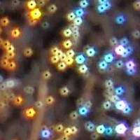
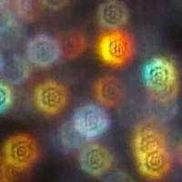
If the sun happens to shine on a cup of hot tea, there is a chance to see colours scampering on the surface. Myriads of tiny droplets are hovering there, forming rapidly changing patterns.
)
The small white or coloured patches on the photographs do not show the real size of the droplets, see the discussion of Fresnel diffraction ![]() given earlier.
given earlier.
Clearly, the water evaporates, but some part of the steam condenses to form the mist. Part of the mist droplets are carried away by the ascending vapour and warmed air, but many of them stay near the surface, pulled down by their weight, but do not merge with the water below, as they continuously collect upwards-directed momentum by the water molecules which condense on them, while the molecules which evaporate from them are emitted in all directions and thus carry no net momentum. Whether there are other mechanisms contributing is still an open question.
A recent investigation [1] showed that the radius of the droplets is about 10 μm and their height above the surface was estimated to be about 10 to 100 μm. The size of the droplets is remarkably uniform and depends on the temperature, above cooler water the droplets are smaller.
)
)
The colours are most conspicuous when looking against the light, just avoiding to see the dazzling reflection of the sun. Iridescent clouds ![]() or coronas around the sun or moon
or coronas around the sun or moon ![]() are well known examples of colours due to scattering by mist droplets and these colours are easily explained; here now the situation is more intricate. Light from the sun is (a) scattered by the droplet to the eye, (b) reflected by the water surface and then scattered by the droplet, (c) first scattered by the droplet and then reflected to the eye, and (d) reflected by the water surface, then scattered, and then reflected again to reach the eye. All these four interfering rays contribute to the same small light patch seen.
are well known examples of colours due to scattering by mist droplets and these colours are easily explained; here now the situation is more intricate. Light from the sun is (a) scattered by the droplet to the eye, (b) reflected by the water surface and then scattered by the droplet, (c) first scattered by the droplet and then reflected to the eye, and (d) reflected by the water surface, then scattered, and then reflected again to reach the eye. All these four interfering rays contribute to the same small light patch seen.
The paths (b) and (c) are those which lead to the coloured Quételet fringes ![]() which are occasionally (but rarely) seen on dusty mirrors or windows. The scattering by the droplets modifies the spectrum of the sunlight, the interference of the light along the paths (b) and (c) modifies it once more, thus the resulting colours are not restricted to those seen in iridescent clouds or Quételet fringes. Presumably, the light along paths (a) and (d) contributes only little, as the scattering angle is much larger and therefore the scattered intensity much smaller than in the other two cases.
which are occasionally (but rarely) seen on dusty mirrors or windows. The scattering by the droplets modifies the spectrum of the sunlight, the interference of the light along the paths (b) and (c) modifies it once more, thus the resulting colours are not restricted to those seen in iridescent clouds or Quételet fringes. Presumably, the light along paths (a) and (d) contributes only little, as the scattering angle is much larger and therefore the scattered intensity much smaller than in the other two cases.
From the fact that, in some regions, the colour changes smoothly we can deduce that there the droplets' sizes are all nearly equal and the same holds also for their heights above the surface.
Indeed, there is little difference in the colours to be seen over hot tea, coffee (without milk) or just hot water. The above pictures were obtained with hot water, but I first saw the colours many years ago when the sun was shining on the breakfast table and there was tea in my cup. And I noticed another remarkable effect: after stirring the tea, small parts of tea leaves still circled around near the bottom of the cup, while small bubbles on the surface did not do so. Apparently, a very thin film had formed at the surface, which did not follow the motion of the fluid beneath but stuck to the rim of the cup. Whether such a film develops may depend on the kind of tea and the hardness of the water. This film does not prevent evaporation and the formation of mist, but it slows down the motion of the tea and the hovering droplets.
After moving, my breakfast table is not sunlit any more and I had not seen these colours for years. But a recently seen Optics Picture Of the Day “OPOD” reminded me of them.
This is not a physical, but a physiological effect. Oranges and tangerines are often sold in bright red nets. This affects the perceived colour of the fruits, letting them appear more attractive, and is a practical application of Munker's illusion.
)
)
In the right image, the tangerine taken out of the net looks somewhat lighter and more yellowish than the neighbouring ones, while in the left picture there is no difference seen.
Below you see six times the same photograph “covered” by differently coloured grids. Clearly, the red colour for the nets is a good choice.
)
)
)
)
)
)
Sometimes one can see a spider web glistening in lively colours, if the sun is behind it and it happens that in spite of that there is a dark background. Such a situation may last only few minutes.
)
)
)
)
)
)
In a photograph, these colours are rendered best if the web is somewhat out of focus, otherwise they fade when the strands are over-exposed. But moreover, part of the colours disappears if the strands are in focus, as then all light rays reaching one point of the sensor have passed the same optical path length and interfere constructively for all wavelengths. If out of focus, the rays reaching one point of the sensor come from somewhat different parts of the strand and may interfere destructively.
Read more on spiderweb optics.
)
)
)
A grey cloud with white border hiding the sun, blue sky and some dark, nearly black trees and shrubs on the other side are mirrored in the waves of a canal.
This and also the next picture remind of abstract painting or drawing. To see how the second photo was taken, click on the thumbnail to its right.
This is not a rare sight: on a sunny day there seem to be reflecting puddles far away on the road, but coming closer they vanish. In a desert, similar reflections by the warmer air near the ground might lead to the illuson of a distant lake.
)
)
Often there are several mirror images of the same object to be seen, in most cases strongly flattened. And on closer inspection one might realize that upside down and upright flattened images alternate.
The multiple images are due to the fact that the road is not ideally flat but slightly wavy, and the reflections by the thin layer of air warmed by the asphalted road are then similar to those on water with gentle waves ![]() .
.
By the density fluctuations due to ascending warm air there are additional distortions of the mirrored as well as the real objects.
)
By a glossy surface, light rays are reflected with a sharp kink. But when the refractive index changes smoothly as is the case here, the rays are only slightly bent along their way. In the sketch to the left the reddening of the air over the grey road surface indicates the temperature distribution. Light rays going from three points of an object to the eye are shown. The rays outside of the heated region are straight (thin lines), the object is seen without being distorted. But the rays drawn with bolder lines first go down and are then bent upwards to convey a distorted mirror image to the eye. As, for clarity, the vertical dimensions are exaggerated, the distortion is also overstated.
)
)
)
This kind of distortion could be seen more clearly if the ground were perfectly flat. Above an expanse of water, if the water is warmer than the air. I have no such picture, but there are some in the web, e.g. this one. But there the main part of the mirror image is flattened! The water surface is not a plane, as the earth is a sphere.
To the right you see the result of a model computation. A stepped pyramid is reflected by a thin layer of warm air and observed through a telescope. The left pyramid is eight metres high and at a distance of 1 km, and the telescope is mounted at 30 cm over the ground. The second pyramid is 200 m, distant 25 km, and observed from 7.5 m height, the third is 320 m high, 40 km far out, and seen from 12 m. The lowest step has already disappeared behind the horizon in the last picture. It is clearly seen that the mirror image is compressed vertically near the horizon. If the earth were a flat disc, the three images would be identical.
Thistle seeds are equipped with fine hairs (pappus) which enable them to be carried by the wind.
Below: seed heads of a creeping thistle (Cirsium arvense), photographed against the low sun. There are two conspicuous optical effects to be seen: the gleaming parts outline circles around the sun, and, when out of focus, exhibit bright colours.
The pictures to the right each show a detail of the neighbouring one; click to enlarge!
)
)
)
)
Light rings have already been discussed – ![]() ,
, ![]() – as well as similar diffraction colours
– as well as similar diffraction colours ![]() ,
, ![]() . But seemingly there is a difference in the appearance of out-of-focus silk strands and thistleseed hairs, the latter showing more vivid colours! Below there is a comparison of gleaming thistleseed hairs (left) with caterpillar silk (right)
. But seemingly there is a difference in the appearance of out-of-focus silk strands and thistleseed hairs, the latter showing more vivid colours! Below there is a comparison of gleaming thistleseed hairs (left) with caterpillar silk (right) ![]() .
.
)
)
The silk strands of the caterpillar web tent probably have a smooth, only slightly wrinkled surface and no structure beyond that. In contrast, the cellular structure of the thin hairs of the thistleseed pappus is likely to form nearly periodic patterns, at least over small distances, which lead to more pronounced interference. In the photo-micrograph below, these patterns may be guessed, but cannot really be seen.
)
)
Creeping thistle seeds under normal light, image width is 6 cm, and a micrograph of pappus hair, image width 1.15 mm. The thin hairs are approximately 0.01 mm thick.
)
The vivid colours shown by compact discs are well known. They are due to diffraction of light by the tightly wound spiral formed by the pits encoding the data in the case of the pressed audio CD or CD-ROM, in the case of the recordable compact disc (CD-R) by the spiral groove (“pregroove”) molded in to guide the laser beam upon writing and reading information. The polycarbonate disc is coated on the pregroove side with a very thin layer of organic dye, then with a thin, reflecting silvery layer, and finally, a protective coating of lacquer.
When using a CD as a mirror to look at a lamp, there is an image showing no colour-splitting, but depending on the viewing angle, distorted diffraction images of first or higher order can be seen. In case of small light sources, in first order almost pure spectral colours appear.
Reflections of a small (or very distant) light source by planes with regularly ordered glossy grooves and ridges will appear as glitter paths, examples have been shown (1, 2). To the right there is a close-up of a small LED lamp reflected in a CD. Here the path which crosses the mirror image of the lamp is interrupted by destructive interference, but the spectra are seen just where the “ordinary” glitter path would also be.
But there is something else, namely another sequence of diffraction images of the lamp along a path which here is approximately in the direction of the grooves. This is reminiscent of the diffraction patterns from feathers. So there is some periodic pattern along the grooves!
‘A blank CD-R is not “empty”; the pregroove has a wobble (the ATIP [absolute time in pregroove]), which helps the writing laser to stay on track and to write the data to the disc at a constant rate’ (Wikipedia).
The two images below again show this diffraction series, to the left when the lamp is reflected near the centre of the disc, to the right when the reflection is near the rim.)
)
Clearly, the periodicity interval of the ATIP is shorter near the centre of the disc then near the rim, therefore the spreading of the spectra decreases with increasing radius.
However, the ATIP wobble produces some more subtle optical effects which can be seen better with enhanced sensitivity, when the brighter spectra are already highly over-exposed.
)
)
The first-order diffraction spectrum is fanned out by the ATIP. Looking towards the centre, we see the reflection by the convex side of the grooves and the fanning angle is reduced (like an image in a convex mirror), while towards the rim the hollow side of the grooves works like a magnifying mirror. The somewhat irregular appearance is probably due to the fact that the ATIP is, of course, not strictly periodic.
And then, though only dimly, the light path can be seen which connects the zero-order reflection with the diffraction spectra produced by the grooves. Due to the near-periodic wobble of the grooves, the extinction by destructive interference is reduced at the borders of the path while it is nearly perfect in the middle region. By this, the path appears to be doubled and faintly coloured.
To substantiate the foregoing, the glitter paths on a disc with less dense circular grooves and an additional “ATIP” pattern has been plotted below for a typical case, left picture. The bright path is due to the grooves, the darker one to the ATIP wobbles. It has been assumed that the lines connecting closely adjacent wobbles spiral outwards as sketched in the figure to the right. Of course, not only the grooves, but also the ATIP wobbles are much more dense on the CD.
)
)
TransmissionIt is also well known that a CD may be used as a transmission grating (a link), as the silvery layer can easily be removed using strong adhesive tape, leaving a transparent, finely grooved polycarbonate disc. The photographs to the right show electric sparks taken with a CD-grating (left) and a transparent film diffraction grating (right) mounted as filters in front of the lens. The CD has approximately 625, the film grating has 500 grooves per millimetre, which accounts for the different spreading of the spectra. The colours do not agree with what we would see. This is generally the case with photographs of spectra. (Click here to see a post-processed image which approximates the visual impression.) |
) )
|
)
When the sun is low or, before sunrise or after sunset, slightly below the horizon, sometimes a vertical pillar of light can be seen. It is due to the reflection of the sunlight by innumerable floating ice crystals. Thin hexagonal plates or snow stars are wobbling about horizontal alignment during their slow descent.
This is very similar to glitter paths seen on water when the sun (or the moon) is near the horizon, or when artificial lights are mirrored. If there were no waves, only a single mirror image of the light source would be seen. But mostly there are waves, and their inclined slopes glint when the light is reflected to the eye. The multitude of glints forms the glitter path or patch.
Usually the waves are sufficiently irregular and the patch is symmetric, its far end is exactly under the light source and the path points to the observer.
The image below to the right shows a simulation of a glitter path, assuming a Gaussian distribution for the inclinations of the surface's facets. This is rather crude as the strong correlations between neighbouring surface elements are ignored. To compensate for this, the number of surface elements considered must not be too large. – For the light pillar, i.e. reflection of light by floating plates of ice, a Gaussian distribution is a very good approximation, the inclinations of neighbouring plates are not correlated.
)
)
)
)
However, the glitter paths are not always straight. If there is a preferred direction of the waves – Minnaert [1] describes this in detail – then the glitter path may be bent. This can be seen most clearly on artificial “wavy” surfaces.
To the right: glitter path on the corrugated sheet cladding of the Médiathèque André Malraux in Strasbourg, France. I found this image on the website of Eva Seidenfaden who kindly supplied the original photograph.
The position and orientation of the building can be found on maps available in the web, the time from the photo's Exif-data, so the sun's position can be determined. Finally from the vanishing points of the horizontal and the vertical lines and edges the direction in which the camera pointed can be reconstructed. Thus, all necessary data are available to determine the glinting spots.
The single waves of the Venetian blinds like cladding were simply assumed to be glossy lines (or thin cylinders) where the angle between the lines and incoming and reflected rays is the same.
The next picture (also courtesy of Eva Seidenfaden, link) shows a splatter guard, essentially a perforated metal plate, held against the sun. A regular array of parallel short hollow cylinders, and this time the glints form a closed path. For the computation, the hollow cylinders were approximated by short lines.
)
)
The essential feature, namely a closed path, is easily reproduced. To obtain an oval instead of a circle, a slight bending of the steel sheet had to be assumed. The much broader path on the photo is due to the roughness of the metal, moreover the punched holes are not strictly cylindric and in addition their orientation varies slightly which explains the irregularities. Of course, all these features could be mimicked as well, but without much gain in understanding.
Some more bent glitter paths have been shown earlier.
)
An example of a Brocken spectre with glory has been given earlier. This picture here has been taken on a flight from Vienna to Hanover in the late afternoon. I was looking for the shadow of the plane.
The water droplets which form the clouds are tiny, their diameter is only few microns. Part of the light entering is reflected at the back sides of the droplets. Due to their minute size, refraction and reflection do not follow the rules of geometrical optics, instead, diffraction and interference effects of the light waves dominate. There is no simple approximation to compute the glory around the antisolar point, but the exact solution of the scattering of light by spherical particles given by Gustav Mie in 1908 is available.
The antisolar point is the centre of the glory; this is where the shadow of the aeroplane would be. But apparently there is no shadow, the cloud there seems even brighter than the surroundings.

An observer floating on top of the clouds at the centre of the glory would see the aircraft obscuring only a small part of the sun's disk. Thus the penumbra of the plane on the clouds is too weak to be seen and, moreover, is outbalanced by the mid part of the glory. Only when the plane is much closer to the clouds there is a distinct shadow. A beautiful image is shown here.
Some time ago I got a mail with three pictures, “Rainbows on a leaf”, and the sender wrote “I was intrigued to find these patterns from tiny dew on a leaf … I am wondering if it is thin film interference …?”
The patterns were vividly coloured stripes across the out-of-focus glints of the drops. The images, taken with an iPhone, were over-exposed and colour saturation had been enhanced, so I decided to get my own photos with a phone camera, and I was reasonably successful.
)
)
Due to the tiny objective lens of the phone camera, expectedly there are obvious Fresnel diffraction effects. But some of the glints are candy-striped while most others are more or less colourless, white or grey. Some of the drops on the leaf are nearly spherical and thus show rainbow colours at the expected angles, while most of them are only more or less hemispherical or irregular. Moreover, there are many different sizes. This explains the different appearance.
|
The colours are quite similar to those seen in thin films, but here there are no thin films. In thin films, the waves reflected at the front and the back side interfere and there is mutual enhancement or attenuation depending on the wavelengths, the thickness of the film, and the observation angle. Interference also causes the multiple coloured stripes. There are three different paths for the light reflected by a water drop at a fixed backward angle, as shown in the sketch to the right. The optical path lengths of the two rays reflected at the back side are slightly different. Their interference produces the coloured stripes, as their path difference is small and depends on the deflection angle. The waves reflected at the front side of the drop add only a little brightness. |
)
|
)
)
In the left picture, the glint to the right shows an over-exposed part of the primary rainbow, while the left one shows its supernumeraries. The right image, taken with a digital bridge camera, renders the colours of the primary bow more faithfully.
|
Generally, when seeing a rainbow, we look at a large number of drops, and each drop contributes just one colour. Here now the situation is different. The schematic sketch to the right illustrates the appearance of rainbow colours in the blurred glints. (Diffraction effects ignored.) A beam of sunlight is reflected by a small droplet as a cone of light (in the sketch we see its cross section), the rim of which forms the rainbow. If now the camera's lens is so close to catch the rays in a large solid angle, the out-of-focus image of this glinting drop on the sensor (A) of the camera looks like the small circle to the right. If the drop were in focus (position B of the sensor), all the different rays would combine again to yield a white (over-exposed) dot. |
)
|
|
Small droplets hanging on a flower's stipe are pictured, like small lenses they show the scene behind them upside down, most clearly the rightmost one. There are similar drops in the background which are severely out of focus and glittering in the same way as those imaged, each of them is effectively a very bright and very small light source, almost point-like. They produce bokeh, shapes of big polygons which are kind of projections of the camera's aperture onto the sensor. The diaphragm consists of nine blades. The nine-sided polygons show typical interference fringes, and in addition a lot of groups of concentric rings. This is seen better in the next photo, click to enlarge! What is the cause of that? |
) |
|
I guess that the lens got slightly misted in the moist atmosphere close to the plants. Each very small droplet on the lens produces its circular Fresnel diffraction pattern, the patterns overlap to yield the impression of a moiré. Of course, ordinary dust can produce the same effect. Another diffraction effect is seen in the star-like appearance of the sun's images in the drops. This is due to the polygonal shape of the aperture as discussed below. |
) |
| Photos © Neil Goosey, shown with permission. |
I have never seen St Elmo's fire outdoors, not to mention taking photos of it. Moreover, the situations when it occurs are scary so one rather does not search for them. But if one wants to see it, electrostatic high voltage generators offer a possibility.
The historical apparatuses still fascinate hobbyists and tinkers, just search for images of influence machines – you will find numerous examples and also construction guidance.
Already for some time a construction kit of a Wimshurst machine is on the market, produced by AstroMedia Verlag in Germany. Wimshurst's machine is the best known of a number of similar ones. Good explanations of its mode of functioning may be found in the web, e.g. whyhow on the pages of Antonio Carlos M. de Queiroz.
)
)
This small machine is different from most others and also from Wimshurst's original one in that the charge is taken only from one of the two rotating disks, and this is done not by combs, but by brushes which are in contact with the disk. But the operating principle is the same and it works very well.
In most cases, corona discharges are not wanted. Here they are harmless and nice to observe if the machine is operated in the dark. (The next four photographs have been taken with 60 seconds exposure.)
)
)
In particular the disk where the charge is not taken from shows distinct corona emission. Noteworthy is the different appearance of the positive and the negative charge emission. In the left image, the positive charges are on the left hand side, the negative charges on the right. The disk is rotating clockwise. It is remarkable that in the lower right the metal sectors on the rotating disk are clearly seen as dark areas surrounded by the light of the corona discharges. This indicates that the discharge is not continuous, but occurs in bursts just at the moment when the brush of the diagonal neutralizer gets contact with one of the metal sectors. This sector, the lowest visible one to the right, discharges on the side first touching the brush in bright sparks while it is sprayed with more negative charge from the next segment. This next segment too gets charge from the following ones.
The velocity of the disk's circumference is about 5 m/sec, the blur of the segments' contours is some tenths of a millimetre at most, from this one estimates that the duration of a burst is only a fraction of a millisecond, probably a very small fraction.
In the right picture, the negative side is in the foreground in the lower half. The positive brush discharge (top) extends quite a distance off the disk, while the light of the negative discharge seems to stick to the disk. This difference can be used to determine the polarity. When operating the influence machine, either side may become positively or negatively charged, depending on more or less random conditions.
If the gap between the spherical electrodes is so large that there are no sparks any more, corona discharges can be observed there too.
)
)
If, in this case, the smaller sphere is positively charged and is opposed to the larger sphere, every now and then, with a little noise, a single faint discharge occurs, resembling a dim spark (left image). The right picture shows the same arrangement, but with reverse polarity. The smaller negatively charged sphere “continuously” discharges with a hissing noise, only a short brush of light can be seen.
)
Watching ducks on a pond one may wonder how these beautiful wake patterns arise. William Thomson (the famous physicist Lord Kelvin) found already in 1887 the remarkable fact that the angle at which the wake fans out is always the same, regardless whether the wake is caused by a duck, a boat, or a ship, as long as the water is deep as compared with the lengths of the generated waves [1].
)
)
| Wakes of ducks on a pond |
Wakes of two boats on Avon Gorge. Photo: Arpingstone, source |
While the mathematical treatment of water waves is difficult, see the Wikipedia article, some results are easy to obtain, and in particular the shape of the wake can be explained using only elementary maths …
Read more.
[1] William Thomson (1887) “On ship waves”, Institution of Mechanical Engineers, Proceedings, 38:409–434 pp. 641–649.
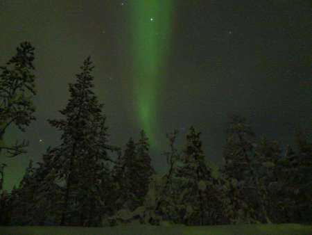
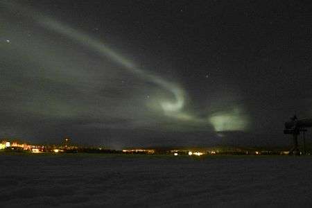
Finland, Lapland, Äkäslompolo, January 31, 2016. During the day the sky is nearly overcast, in the evening it is snowing. But after midnight one can see the brighter stars, and a glowing belt crosses the sky. There seems to be no colour. But not so on the photographs!
)
The sky is dimly gleaming reddish, greenish near the horizon, and a band of green light crosses it. (White point: 6500 K)
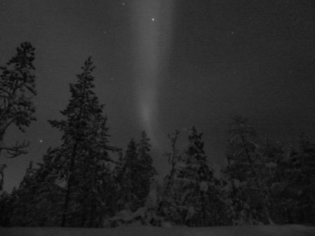
| Automatic white balance by the camera (4577 K set to white) | This is what I saw. |
Slowly billowing the light changes shape, size, and intensity, diminishes and gets stronger again, stretches from horizon to horizon, a weird spectacle, until after some two hours the veil of clouds gets denser.
On some websites you might find sentences like this one: “Generally photos or photographic animations of the aurora exhibit too strong colour saturation and therefore do not agree with the actual sight.”
This, however, is not strictly true. Often there is only one strong spectral line in the light, it is therefore more saturated than any possible reproduction on the screen or in print – it is only that we cannot see it. We could see this colour if the lights were much brighter.
At very low illumination levels, only the rods in the retina are active. They evoke the sensation of light, but without colour (scotopic vision). At somewhat higher illumination level the cones contribute some colour (mesopic vision). Therefore, only very bright northern lights are seen coloured.
The fading of colours when it gets dark is a feature of our visual sense, in photographic cameras it is not built-in. Photographs shall reproduce the colours as we see them when we see them, and this requires considerable effort as our visual sensitivity adapts itself to a wide range of illuminations. In the camera this adaptation is mimicked by the white balance. In most cases the automatic white balance works very well, for special cases some standard settings are provided as well as the possibility of manual setting.
But what to do if it is dark, if no colours are seen? If possible, choose the RAW format for the digital image, then the white balance can be chosen afterwards. Clearly, there is no “correct” white balance in this case. A black-and-white image is easily obtained from a coloured one, but if colours are wanted, the white balance is quite arbitrary. My preferred choice is “daylight” D65, approximated by colour temperature 6500 K, as on the screen white is set to D65 if the sRGB colour space is used.
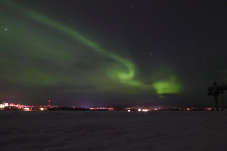
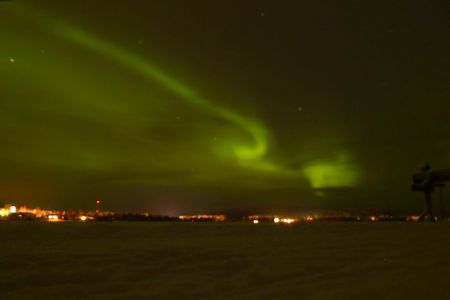
| Automatic white balance (4667 K, shifted towards magenta) | 6500 K set to white |
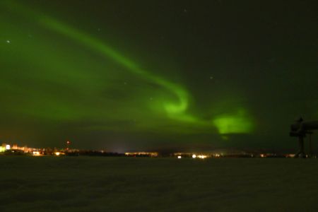
| 5000 K set to white | Colour saturation strongly reduced except for the artificial lights |
For bright northern lights when colours have been seen, post processing cannot be avoided if one wants to render the visual impression. Certainly most of the many images found in the web do not show the aurora exactly as the photographers have seen it.
A little bit more on the underlying physics.
)
It is one of the more common halos, but nevertheless most people don't know this “smiling” bow high up in the sky. When the sun is low and there are thin cirrus clouds one should look for it. Sometimes it is only faint (02.11.2015) or almost invisible (26.20.2015), on the image above from December 25, 12:02 CET it is also quite faint, but clearly visible. This arc has already been explained in the section on refraction.
)
In the waves of a barge's Kelvin wake the trees on the other side of the canal are reflected. (Against the low sun, the barge is hardly visible.)
)
In the nearest reflection seen at the bottom of the image the trees are strongly distorted but clearly upside down, in the next one above they are upright (though canted), then the sky is reflected, followed by upside down trees, erect trees, …
The ray-tracing sketch to the left illustrates the reflections at the waves' troughs and crests.
But there is more detail, as shown in the image below. Starting at the bottom, first the reflection of the bluish grey sky is seen, with thin clouds and white contrails.
)
Then there are the upside-down trees, followed by a dark area – the body of the vessel. Then comes the image of the water, the next wave which shows again the compressed background scene, changing between upright and upside down several times and therefore quite blurred. This is followed by an upright, but strongly tilted and distorted image of the dark vessel, the trees, and the sky above with its contrails, the zig-zagging of which is due to small gentle waves on top of the large ones. This sequence is repeated several times.
)
Late autumn, gentle rain. Wet twigs of a walnut tree gleam in the light of a street lamp and seem to outline circles around the lamp.
This has already been explained by M. Minnaert in his famous book [1].
)
Consider a small plane V, reflecting the light of the lamp to the eye. All the little twigs in that plane glisten. But due to perspective twigs like AB are greatly shortened, whereas those like CD show their full length. Though branches are found in many directions, we shall see mainly light lines at nearly right angles to the plane ELV. Similar arguments hold for other small planes like V' and others which we might imagine above, to the right or left of the light source. This leads to the impression of concentric circles.
Such light rings or light circles are seen when light is reflected or diffracted by more or less randomly distributed elongate structures.
)
To the right a computer simulation shows objects resembling thistle seeds. From the centre of each seed 18 hairs (lines of equal lengths) radiate, the directions determined by a random number generator so that all orientations are equally likely. In the background, a point-like light source is assumed. Whenever the angle between the light ray from the lamp and a hair and that between the hair and the light ray from it to the eye differ by less than one degree the line is drawn in white, otherwise in grey. The seeds are randomly placed in three-dimensional space and a stereoscopic image pair is generated. The left image is for the left and the right one for the right eye. In the enlarged picture (click!) it is the other way round, this has to be viewed squintingly. If you succeed to merge the pair to one 3-d image, you may notice another interesting effect: the hairs really seem to glitter! I attribute this to the fact that the gloss is not the same for both eyes.
Caterpillar silk and scratches are other examples which I have shown earlier.
[1] M. Minnaert (1937): De natuurkunde van 't vrije veld. Licht en kleur in het landschap. — The nature of LIGHT & COLOR in the open air. Translation by H.M. Kremer-Priest; Dover Publications Inc., New York 1954 ISBN 0-486-20196-1
Below you see the bottom of a stainless steel frying pan illuminated by a single light bulb. Two optical effects are clearly visible, circular light rings around the over-exposed, diffuse mirror image of the lamp, and a bright shining path. The close-up to the right shows the central part of the pan and the causes of the effects, namely concentric grooves from machining which produce the bright path, and also some of the numerous scratches from frequent use which form the light rings.
)
)
The grooves and the ridges separating them as well as the scratches are shining when the condition of specular reflection is fulfilled for part of their surface. Because of the roughness of the surface on a microscopic scale, and because of the size of the light source, it is always a short piece of the scratch or ridge, not only a point which glints. In the picture these short glossy lines are nearly tangential to circles around the point where the mirror image of the lamp is (or would be if the bottom were flat and glossy), or nearly orthogonal to a radius drawn from the mirror image of the lamp. (Nearly orthogonal because of the oblique view on the pan.)
Almost everywhere there are some scratches in the right direction to glint and so we get the impression of numerous short pieces of circular rings. (The centres of the rings are slightly below the lamp's mirror image, the more, the larger the rings are.) If one would trace the rings on the bottom of the pan, one would get ellipses.
)
)
The frying pan is seen below, here the blazing path is two-branched and reminds of a hyperbola.
)
)
The regular circular grooves and ridges reflect only along a path which goes through the central point of the pan and through the mirror image of the lamp. The simulation to the right is a perspective view of an imclined plane with circular “grooves” (glossy lines). The geometry has been chosen to imitate that of the left picture, and the bright path is nicely reproduced.
The gloss depends strongly on the viewing angle, and in most cases both eyes see quite different glosses. But sometimes it happens that the glitter paths seen by the left and right eye differ only slightly and stereoscopic vision evokes the illusion that there is a glittering ray crossing the pan, being partly beneath and partly above it. This may be seen in the following stereo pair of images, if you can squintingly look with the right eye to the left and with the left eye to the right picture. (Placing your thumb somewhere between your nose and the screen and looking at it while moving it slowly back and forth may help to merge the two images.)
)
)
)
You can't see a rainbow from the side or from behind. But it is possible to stand behind (or in) a rain shower which might show a rainbow to another observer. If the sun is low and a rainbow is seen, it may be worth while to look also in the opposite direction. The sky may glow in the colour of the setting sun, as in the right picture above.
In connection with the classification of rainbows, this phenomenon has been called “zero order glow”. Only a small part of the light incident on a rain droplet is reflected at the rear side to form a rainbow. Most of it passes through and is scattered by refraction into a wide solid angle.
)
A rainbow can only be seen where the water drops are. Thus, in the picture to the right, it is certainly closer than the sailing boats. But if the distance is measured by triangulation, it turns out that the bow is infinitely far. It is no material object. Its centre is the antisolar point. For the bow seen with the right eye, the centre is the right eye's antisolar point, and for the left eye's one correspondingly. Thus, stereoscopic vision should correctly see it infinitely far away. However, for a diffusely edged object, stereoscopic vision may be overruled by other hints on its distance.
 |
| Photo © Mathias Müller (site), shown with permission |
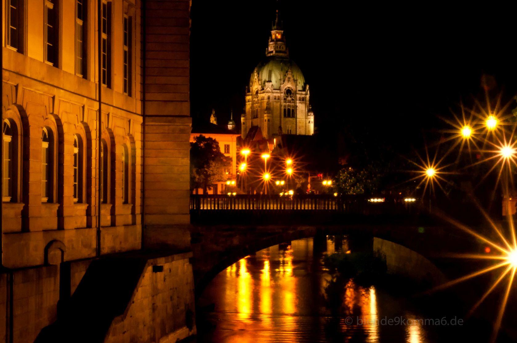
The above photograph, a view of Hannover at night, aroused my curiosity because of the beautiful stars around the street lamps.
The stars are certainly diffraction effects due to the shape of the camera's aperture. To demonstrate that, I computed the images of a point-like, monochromatic light source for a variety of shapes, the figures just below show results for a seven-bladed aperture diaphragm. For the photograph above, the focal lengts was f = 42 mm, and the aperture was f/32. I used those values and the wavelength of λ = 555 nm.
)
)
)
)
The first image in the row shows a pattern which looks very much like the Airy disk of a circular aperture. The width of the image corresponds to 0.2 mm on the sensor of the camera. The brightness of the consecutive diffraction rings falls off very rapidly and no starlike shape is seen. This changes if the brightness is increased so that the central spot is severely overexposed, as shown in the next figures, the widths of which is now 2 mm. In the first, second, and fourth figure, the light source is in focus while in the third one some defocussing is simulated. The last image differs from the second one in that the blades of the diaphragm are slightly curved.
In the spikes of the stars interference causes alternating light and dark regions. These are never seen in this clarity on real photographs for two reasons. Firstly, most light sources are not point-like, they have a finite extension which blurs the image, and secondly, they emit light which is a composition of many different wavelengths, while the computation was done with a fixed wavelength (monochromatic light).
I took two pictures of a nightly scene in a more rural region, one with aperture f/8, the other one with f/3.2, which is the widest opening at the given focal length. Clearly, the star-like appearance of the street lights is due to the shape of the aperture of the diaphragm which in this case is a hexagon formed by six slightly curved blades.
)
)
Below some more computer-generated pictures are shown which illustrate the influence of the diaphragm on the image of a point-like monochromatic light source. (For better visibility, grey-scale images instead of green ones are presented.) The following parameters have been used: wavelength λ = 555 nm, aperture D = f/8, focal length f = 10 mm.
Click to enlarge!
)
)
)
Left: Hexagonal aperture, image width 0.06 mm. No overexposure of the central spot.
Middle: The same hexagonal aperture, image width 0.6 mm, central spot overexposed 3000 times.
Right: Hexagonal aperture formed by slightly curved blades, overexposed 3000 times
It is seen that the curvature of the edges leads to diffusely ending prongs of the stars.
READ MOREFor RealD® 3-D movies the viewers have to use special glasses which look like sunglasses. The lenses are filters which either block circularly polarized light or convert it to linearly polarized light which then is seen. The image for the right eye is polarized right circularly and is blocked by the left lens (and vice versa). If lit from behind, the right glass creates right circular polarization, the left one performs correspondingly.
Two pairs of RealD 3D glasses are used for the following pictures.
)
)
)
Note that in the left image, the dark areas are not black, but dark purple. In the middle image, where the first glasses are rotated, the dark area is black. Looking aslant through the opposed glasses, blue and brown colour is seen.
Our eyes are not equipped to detect polarization. Moreover, circularly polarized light is rare in natural environments. Therefore, the following photographs, except the first one, seem to be weird.
) |
) |
) |
) |
) |
)
|
What you see is due to the fact that the handedness of circularly polarized light is flipped when reflected by a metallic surface, and that the light reflected by the glass plate is linearly polarized at the chosen observation angle.
Visualization of circular polarization and somewhat more elaborate explanations are given HERE. The RealD technology is described on RealD's homepage in the corresponding section.
The reflections of the sun in the eyes of dragonflies have a striking similarity with patterns arising from Fresnel diffraction, though, seemingly, the conditions are quite different.
) Anax imperator, blue emperor |
) Orthetrum cancellatum, black-tailed skimmer |
) Aeshna cyanea, blue hawker |
) Aeshna cyanea, blue hawker |
The compound eye of a dragonfly consists of several ten thousand facets, each facet formed by an ommatidium. The facets are so small that they are not resolved in the photographs above, even though they are in focus. My first idea was that each pixel of the camera's sensor receives light reflected from some more than one ommatidium, and these waves are superposed and interfere. This is certainly true, but does not yield the observed pattern. The corresponding maxima and minima are not resolved, as a quantitative estimate shows.
Instead, the reflection from single facets shows intensity variations which are indeed very similar to those of Fresnel diffraction.
| To substantiate this interpretation, I have computed the reflection of light of 550 nm wavelength by a tiny convex mirror with curvature radius 2 mm in the shape of a regular hexagon with edge length 0.1 mm (generalising Kirchhoff's formula to the case of reflection on a surface). The result is shown in the image to the right; the image width is 5.73°. |
)
|
If now a larger sphere is parqueted with such tiny hexagonal mirrors (most of them must be slightly distorted, and some pentagonal ones are also needed), the reflection of a point light source would also look like the image above. The simplest geometry has been assumed for the computation, observation from the side of the light source, which is only possible if the observer is transparent or at least point like.
The other peculiar feature is the pattern of dark diffuse spots distributed over the dragonflies' eyes. This is a moiré, it depends on the viewing angle and distance.
In the focal area of each ommatidium's optical system (formed by the cornea lens and the crystal cone beneath) there is a dark spot – the retinula (upper end of the light-sensitive rhabdome), possibly surrounded by dark pigment, and between the dark spots the tissue is pale. Looking into the facets, one sees either the pale tissue or the dark spots of the same, the neighbour, or next neighbour ommatidia, depending on the viewing angle, and this forms the pattern of the moiré.
There is a discontinuity in the moiré pattern which reflects the discontinuity in the facets' sizes. The ommatidia looking up or backwards are larger than those looking forwards, downwards or to the sides, and correspondingly the pattern there is coarser.
| The image to the right shows a nest of the ermin moth Yponomeuta evonymella on a Bird Cherry shrub. (Click on it if you want to see it in real size!) For most of us, web tents of moths' caterpillars are an unpleasant sight. However, the entangled silk strands can show interesting optical effects! An unoccupied part of a tent is shown below, photographed against the sun, getting closer and closer. |
) |
)
|
)
|
)
|
)
|
|
|
)
|
The mazy strands of the web glisten, and the glistening parts seem to form concentric circles around the sun. The gloss is bright where the condition of specular reflection of the light rays is approximately fulfilled.
To see how the rings arise I have done a crude simulation. A random number generator has been used to create coordinates and directions of lines in three dimensional space, and the points where the light rays would be reflected to the eye by the lines were determined. Short pieces of the lines have been drawn to either side of these points to account for the slight roughness of the silk and for the width of the sun's disc. |
) |
Now to the colours! In this case of very thin strands and in forward direction, the main contribution to the light reaching the (camera's) eye is neither from reflection at the surface nor from refraction by the transparent silk, but from diffraction, which means the propagation of the light waves into the shadow region. (This is analogous to the scattering by small droplets, see the comparison in the section on Mie scattering.) Babinet's theorem then tells us that the diffraction pattern is the same as that of a small slit in a diaphragm.
Scattering by thin fibers can be seen on spider webs, another example has been given in the main section on diffraction. There, the colours are ordered and show the same sequence as those in the diffraction pattern of a narrow slit. Here now, the colours seem to be distributed quite randomly. This can be attributed to varying thicknesses of the strands.
In photographs, blazing colours are rendered better if the gleaming objects are somewhat out of focus. In the last two images, the out-of-focus fibers are not simply blurred, but are split into two, three, or more parallel diffuse stripes. This is due to interference in so-called Fresnel diffraction.
)
|
)
|
Photos © Julia Wilksen
The greenhouse is covered with colourless translucent polyethylene sheeting, but the reflections of the sheet in the puddles on the floor are coloured. Blue might be due to the blue sky above, but purple, pink, and straw and greenish yellow?
This is a nice example of colours arising from polarization without special polarizing filters. The chain molecules in the PE foil are partially aligned which causes birefringence. The incident light from the blue sky is polarized, and the reflection by the puddles substitutes the analysing filter. For details and other examples see the section on polarization colours.
An aureole of radial rays seems to surround the shadow of my head in the turbid water of a river.
)
|
)
|
The rays are the regions of the water where the light is concentrated by the surface waves and ripples. These regions are very elongate, sheet- or ribbon-like with diffuse boundaries. Their centre lines are more or less parallel to each other. For the viewer, due to perspective, they all are directed towards the antisolar point which is the vanishing point for the parallel rays, and one can see them because suspended particles scatter the light. Stereoscopic vision is hindered by the diffuseness of the brighter and darker regions and, moreover, by the refraction at the rippled surface and its permanent motion. Therefore the appearance is that of a radiant aureole.
) | Rays of sunlight refracted at a rippled water surface. |
)
| Bright lines seem to be arranged radially. However, this is a stereoscopic pair. If you succeed to look at it with crossed eyes to see it in 3D, you see that the lines are parallel. |
Clouds near to the sun very often show iridescent colours, but due to their dazzling brightness this is not noticed in most cases. Reflection in a puddle provides a convenient occasion to observe this, in particular if the sun is obscured by denser parts of the clouds.
) |
) |
) |
) |
A puddle on a path through a peat bog and reflected clouds.
These iridescent colours are mainly due to diffraction.
Ott Rovgeisha captured this backyard-scene in Estonia. He writes: “I noticed a bonfire smoke being bluish, while the corresponding shadow was actually reddish! [. . .] One can clearly see that the shadow of the white smoke is gray, while [that of] the blue one is reddish.”
|
Essential oils and water evaporating from the spruce needles and twigs and condensing in the cool air form the smoke. Its apparent colour depends on the size of the droplets. If they are small as compared to the wavelengths of light, the short waves are scattered much more than the long ones (Tyndall scattering) and the smoke looks bluish. The transmitted light lacks the shorter wavelengths and therefore is yellowish, orange, or red like the setting sun. This giver the reddish shadow. Larger droplets scatter more and also all wavelengths more uniformly (Mie scattering) which makes the smoke look white, and multiple scattering quenches all colour effects. |
) Photo © Ott Rovgeisha |
February 3rd 2015, full moon. A thin veil of clouds hides most of the stars, but Jupiter can be seen in the vicinity of the moon. (The second image comes closest to the visual impression of the scene.)
)
|
)
|
)
|
)
|
Aperture f/3.5, shutter speed 1/6, 1/2, 2, and 4 seconds, 100 ASA.
The corona (or aureole) arises from light scattering by the tiny droplets in the cloud, and only if the cloud is so thin that multiple scattering does not blur the angular distribution. What we see is mainly due to diffraction; if the droplets were opaque, black, the effect would be much the same, as the comparison with the exakt computation shows.
One winter in the 1970s the weather was very calm for several weeks, with temperatures only slightly below the freezing point. The Steinhuder Meer (a lake in northern Germany) was covered by mirror-like ice which eventually was thick enough to sustain hundreds of skaters and walkers.
In regions not yet scratched by the skaters, some areas glinted in the sunshine, others did not, many areas showed small hexagonal gas inclusions, and from this one could see that the ice consisted of very large monocrystals.
)
)
The width of the left picture is approximately 50 cm. The monocrystals can be distinguished by the orientation and shape of the small air inclusions which form flat hexagonal prisms if the crystallographic c-axis is vertical. The right image is about 1 m wide; one monocrystal is glistening.
)
)
The two images above are about 15 cm wide. Small pieces of rime on the surface are out of focus. The hexagonal flat air inclusions are parallel to the surface and all oriented in the same way, but at different depths and therefore most of them are out of focus too.
Mostly, air inclusions in ice are rounded and, as seen from above, with circular circumference. The shape of the small bubbles trapped under the sheet of ice does not change much when freezing in rapidly. Here now, the freezing proceeded so slowly, that the equilibrium shapes could be reached which are, as we see, very flat hexagonal prisms.
In addition to the numerous hexagons there were other shapes of inclusions or impurities for which I have no good explanation: six-pronged stars and diffuse ojects, reflecting the crystal's structure. Both are shown in the pictures below at somewhat larger scale.
)
)
The width of these images is about 7 cm.
Photographs taken at the summit of the Kandel near Freiburg/Breisgau in the morning of New Year's Day 2015.
)
)
Photos © Ivo Zawischa
Mist was coming up when the sun shone.
The water droplets of the mist are tiny, their diameter is only few microns. Part of the light entering is reflected at the back sides of the droplets. Due to their minute size, refraction and reflection do not follow the rules of geometrical optics, instead, diffraction and interference effects of the light waves dominate. There is no simple approximation to compute this (in contrast to diffraction by a pinhole aperture of similar size), but the exact solution given by Gustav Mie in 1908 is available.
The antisolar point is the centre of the glory; this is where the shadow of the observer's head is. If there are several people, each of them sees only the own shadow. This once appeared eldritch to a group of wanderers on the Brocken in the Harz mountains, and they called the shadow on fog or mist the Brocken Spectre.
One evening in late October 2012 it got quite cold after a short rainfall, and I noticed that there was fern frost on the outer side of an inclined garret window of an unheated room. The nearly full moon illuminated the scenery, and I took some pictures. Next morning soon after sunrise, the frost was still there and I got additional pictures, the frost now illuminated by the sun low in the east and a blue-sky background.
)
)
)
)
The images to the right show details of the left ones.
The frost resembled ostrich feathers, but what I have never seen before was the nearly periodic structure of each of these feathers which leads to this regular glittering patterns. The average distance of the bright spots is 13 mm. Though this is rather a phenomenon of crystal growth dynamics than an optical one, it is so strange that I want to show the images.
Images of frost with similar structures can be found in the web: (1), (2).
|
The ideal shape of an ice crystal with small surface area is a prism with hexagonal base. Depending on temperature and humidity, snow flakes develop quite different shapes, see the morphology diagram in the Snow Crystal Primer and the pictures in the galleries of the SnowCrystals site. |
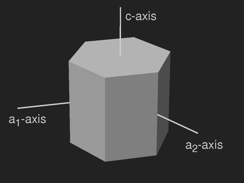 |
The sweeping curves of the monocrystals could be induced by a temperature gradient which distorts the lattice and leads to stacking faults. Curving up or down is possible for the internal lattice, but not for the dendrites which stick to the glass substrate. The frost tends to develop crystal facets, the orientation of which is dispositive for the glittering. Presumably the crystallographic c-axis is parallel to the glass and orthogonal to the growing dendrite. A change of the lattice orientation by 60° then corresponds to the periodicity interval of the feather-like structures. This is illustrated schematically by the following picture.
)
Dew was condensing on a garret window and produced a nice elliptic corona around the lamp on the other side of the street.
)
)
|
The aureole was shrinking and after a while, the colours were gone. The image to the right, taken with daylight, shows the street lamp, the twigs, and the window approximately in the same position as before. The elliptic shape is clearly due to the slant of the window pane. But the aureole is quite different from those produced by airborne particles, which are brightest in the middle. Here the central region apart from the light source is dark. |
)
|
Why is there a difference between aureoles produced by airborne droplets and droplets sitting on glass?
The distance between droplets in a cloud or mist is always much larger than the droplets' diameter. Therefore, their spatial distribution is quite random. Whereas there certainly is interference of the wavelets scattered to the eye by different droplets, this mutual enhancement or depletion occurs randomly and by millions of wavelets, so that finally all the interferences are averaged to zero. Therefore, the interference terms can be ignored and it is sufficient to consider the scattering by a single droplet to understand the corona.
In contrast to this, the dew droplets condensing on a surface may be very close to each other. When they touch they tend to merge to larger droplets. And the second difference is that now only a small mumber of scatterers contribute their wavelets to a single point on the sensor or the retina. Therefore, the interference of waves coming from all the different spots which are not resolved in the image is most important.
One gets already a good approximation to the aureole if one assumes that the droplet behaves like a black disc (image). For a first approximation, we assume that also the droplets sitting on the glass behave like black discs. And for simplicity, we first look at the one-dimensional case: instead of a circular disc consider a thin black wire or, in accord with Babinet's theorem, diffraction by a single slit as a model for the airborne droplet, and a not too large number of adjacent slits to model the spaces between the droplets on the glass. Then we are back to the discussion of single and multiple slit diffraction given at the beginning of the section on lustre and iridescence.
Considering only the colours and intensities along one diameter, the pattern looks indeed more similar to that of a diffraction grating than to that of a single slit. If the lamp were smaller, “point-like” so to say, instead of blue, then white and then red rings the colours would probably be blue, green, and red, as seen in a dim spectrum (see the discussion of the prism).
While there is no long range order in the positions of the droplets, there are short ramge correlations, and this is sufficient for conspicuous interference effects. This is demonstrated by the following computer simulation:
) |
) |
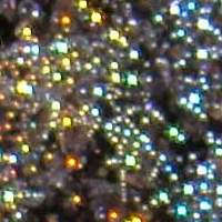
Spider webs close over the moist ground have collected dew drops and glitter in the sunlight. Rainbow colours are easily seen, but not easily photographed. As the colourful reflexes are very small and very bright, they are severely over-exposed, and they all appear white with only a slight diffraction halo in their true colour (left image). The thin strands of spider silk are not visible. If, however, the image is out of focus, over-exposition is avoided and the colours are shown. The droplets deviate more or less from the spherical shape as they stick to the silk, and therefore the coloured patches are not so regularly ordered as in a rainbow.
)
) |
The images of the single reflexes are not just blurred, being out of focus, but show peculiar patterns. The hexagonal shape is due to the diaphragm. Along the inner dark lines the incoming waves interfere destructively. (Click on the picture to enlarge it.) What we see here is an example of what is called Fresnel diffraction.
The next pictures are arranged in order of increasing defocusing.
 |
 |
 |
| a | b | c |
In the case of a true point source and an ideal optical system the interference patterns would be more regular; whether the irregular fluctuations are due to the shape of the tiny rainbow reflexes or to imperfections of the camera's lenses, I do not know.
| It is not difficult to understand what is going on. First consider the schematic illustration of the imaging of a point light source by a lens. The light waves are symbolized by alternating white and black lines. The lens refracts the incoming light, so that the bundle converges. The diaphragm then reduces the cross section of the converging beam. Finally, all the remaining light seems to be concentrated at one point of the image sensor or photographic film (purple line). |
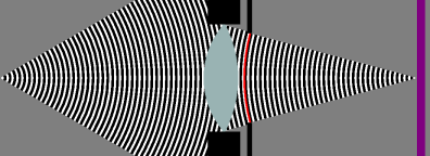 |
This simplified description ignores the wave-nature of light and is therefore only an approximation. To see (and compute) what really happens, we invoke Huygens' principle.
| According to Huygens' principle, in the aperture of the diaphragm, each point of the surface marked by a red line may be considered to be the source of a new spherical wavelet. All these wavelets have to be summed up at each point of the sensor, taking account of their relative phases. In the image to the right, only two of the elementary waves are sketched, and it is seen that the two waves interfere, cancelling each other along the lines which, in the picture, are uniformly grey. | 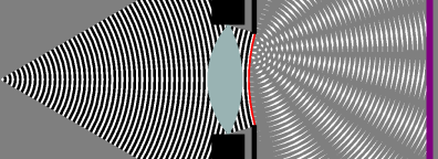
|
Instead of adding only two elementary wavelets, all of them are summed up by integrating over the aperture. This has been done numerically, and the resulting intensity on the sensor is shown in the following pictures, assuming first a circular aperture and then a hexagonal one, starting with a focused image and increasing the defocusing successively. As a measure of defocusing we take the distance from the front surface of the sensor to the focus behind it.
)
)
)
)
)
)
)
)
)
)
)
)
A chain store of Rossmann in the industrial park of Wunstorf, Germany:
)
)
The front of the store is clad with horizontal battens; the cladding is continued as a high fence to the left. The side of the building has a corrugated paneling, the horizontal lines of which have the same spacings as the battens of the fence. This yields a beautiful huge moiré if seen from some distance, the dark fringes being hyperbola segments. Has this been intended?
The next image (the left one) shows the superposition of horizontal stripes (in the middle) with stripes converging towards a “vanishing point” (right image). The distances are chosen to be the same along the vertical centre line.
)
)
)
In many cases moiré effects are a nuisance, e.g. when scanning a half-tone printed image or displaying a pattern of narrow lines on a TV or computer screen. Moiré seen in the middle or right image above is due to the finite resolution of the screen and not pertinent to the picture. Even the left one may look better when it is enlarged (click!).
A car at the roadside, the colour of which changed when I passed by, aroused my curiosity. I just had to take some pictures.
)
)
Searching images in the web was successful. In connection with car finishing, the pigment ChromaFlair® is mentioned, a synthetic multilayer pigment manufactured by JDSU Inc., which is used for car paint and many other applications. (There is an article in Wikipedia which lists also the names of pigments made by competing companies.)
The pigment consists of thin flakes of 20 μm average diameter and 1 μm approximate thickness, the composition of which is schematically shown below:

None of the layers is chromatic, the colour comes about in the same way as in soap bubbles, nacre, or iridescent beetles, by the superposition of the waves reflected at the different boundaries, which leads to enhancement, weakening, or even extinguishing, depending on the wavelength and the angles of light incidence and view. The colours seen are determined by the thicknesses of the glassy and the chromium layers. The flatness of the flakes causes very good leafing properties, producing the metallic lustre.
A rainbow is a rare sight, and sometimes rainbows are quite peculiar. The pictures below have been taken in April near Bad Zwischenahn in Germany with a mobile phone camera.
Near the horizon, where they are brightest, primary and secondary rainbow show their well known sequences of colours. Not so in the upper part, there the primary bow is split, “twinned”, while the secondary bow does not show any irregularity.
)

)
)
Photos © Julia Wilksen
| Small raindrops are spherical due to their surface tension, larger ones deviate from sphericity, they are somewhat flattened by the passing air. The graphic to the right shows a ray-tracing simulation (source) of rainbows of spherical and of oblate rain drops. |
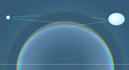 |
If now nearby there is a shower of large oblate drops, while behind there is a curtain of small spherical ones, we see the superposition of the two bows, a twinned or split rainbow.
Though it was not on the shopping list, when we saw fillet of ham gleaming (right image below) we could not resist buying it.
Many people do not like the gleaming of meat as they mistake it for a sign of degradation. But if it is a sign at all, then its meaning is rather the opposite, namely that the microscopic structure of the muscle is not destroyed.
) |
)
|
| Sliced pork | Cured ham |
The iridescent gleaming occurs mainly when the meat is cut across to the muscle fibers. The meat – striated muscle – consists of fibers which in turn are bundles of fibrils. If the fibrils are perpendicular to the surface, their striae are parallel to it, thus forming stacks of layers where the index of refraction changes slightly at each boundary. This leads to iridescence similar to the well known examples like nacre or labradorite, and is discussed in more detail in the section on lustre and iridescence.
Sometimes empty returnable bottles, especially if afloat for a long time, show faint iridescent colours. It is the inner surface of the glass which is covered by a thin film of liquid water. Normally water would run together to form droplets on a glass surface – why doesn't it do so?
Water leaches out, albeit slowly, the alkali components of the glass. Apparently this increases the wettability of the surface, i.e. the mutual attraction between glass and water. This is the beginning of weathering.
)
)
)
WeatheringWhile the colour fringes in the water bottles are not stationary, they change and disappear completely when the bottles are dry, the iridescence of truely weathered glass does not change noticeably any more. If the alkali is leached out from the surface layer and the silica rich remnant then partially crystallizes, it is likely to get small fissures and to separate from the bulk, thus making the layers beneath accessible to weathering. This process can repeat itself, and in the course of decades, centuries, or millenniums the surface may be transformed to many thin silica layers alternating with air-filled gaps. Therefore glass which has been exposed to humidity or buried in the ground for a long time, often shows beautiful iridescent colours. The image to the right shows a brown beer bottle likely dating between about 1910 and 1919. Photo © Bill Lindsey (site). Click for a closeup. Very beautiful examples may be seen in museums' collections. |
) |
)
Two glass gutturnia (sprinklers) from the eastern Mediterranean, 4th–3rd century b.C.
More on thin film and multilayer colours
Special foils named “light effect foils”, “star effect foils” or “3-D effect foils” may be found in some crafts stores. These inconspicuous PVC foils look like transparent paper but have remarkable properties. A small light source looks like a star when seen through the foil.
)
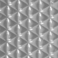
Left: a candle flame in a glass wrapped with “star effect foil”. Right: the microscope reveals the secret of the foil: one side is formed to a pattern of tiny triangular cushion shaped lenses. The image width is 0.6 mm approximately.
)
)
Looking through the foil at a small, “point shaped” light source (an LED is fine), a much more structured star can be seen.
)
)
Left: The centre of an especially regular star zoomed in shows the diffraction pattern of a triangular lattice, see figures (d) and (e) below. Right: The colours resemble those of soap bubbles.
The patterns are due to an interplay of refraction, diffraction and interference.
Simulations with simplifying approximations may help with the interpretation. Starting from Huygens' principle (or rather Kirchhoff's formula), I computed what would be seen when
(a) looking through a single triangular lens at a monochromatic green point source
(b) looking through two adjacent triangulenses at a green and
(c) at a point source emitting red, green, and blue light, each of only a single wavelength.
(d) A 4 by 4 point-lattice, tiny holes (white) in an intransparent diaphragm, and
(e) the diffraction pattern of this 4 by 4 point lattice.
) |
) |
) |
) |
)
|
| (a) | (b) | (c) | (d) | (e) |
A light beam passing a single triangular lens produces a triangular spot of interference fringes bounded by diffuse caustic lines. The superposition of light from two neighbouring lenses produces the macrostructure of the interference pattern. As the position of the intensity maxima and minima depends on the wavelength, with white light there occur coloured fringes. The many neighbours, next neighbours and so on, lead to a pattern of narrow dots and stripes.
When the sun is shining on the sructured side of the foil, there appear colours reminding of soap bubbles or oil films on wet pavement. Below at left such a foil is shown lying on dark grey paper.
)
) |
This seems to be different from what has been discussed so far. Coming close to the foil, one can see very bright reflections, the shape of which depends strongly on the incidence of the light and the orientation of the foil and is not easily describable, and much fainter ones which are part of a large, only partially visible six pronged star (right image).
There is reflection by the structured upper side of the foil and also by the smooth rear side.
Reflection at a triangular convex element at the surface is not specular; due to the smallness of the cells diffraction and interference effects prevail. According to Huygens, each point of the pulvinate surface can be considered to emit an elementary wavelet. All of them have to be added with their proper phases to yield the reflected wave, and due to the camber, the phases are varying strongly over the surface of one cell. This yields wavelength dependent maxima and minima and thus colours depending on the viewing angle.
Light which is reflected by the smooth back side of the foil has already been refracted by the triangular bulges at the upper surface and is refracted once more when going back. Due to the smallness of the bulges, refraction does not obey the laws of geometric optics either, here too diffraction and interference are the cause of colours.
To discriminate between the two mechanisms, I painted the back of a foil with black acrylic varnish which has approximately the same refractive index as the foil. This eliminates the reflection at the rear side – and the bright and more conspicuous colours are now absent.
) |
)
|
Left: Two star effect foils on a dark background, the right one with black varnished back side, lit with a small white LED lamp.
Right: The foil with black varnished rear also shows coloured reflections, though much less bright.
Looking through two superposed star effect foils a moiré pattern occurs as expected. By a slight rotation of one foil against the other, the size of the pattern can be changed. With diffuse illumination, this is not particularly spectacular as the first two pictures show which were taken against the overcast sky. But with a small, “point-like” light source, the interplay of the moiré effect with the refraction by the triangular cells of the foils produces fancy patterns.
) |
) |
) |
) |
) |
| The images above have been taken with the foils in tight contact. In the next two images to the right there is a minute gap between the foils. |
) |
) | ||
Occasionally one may see traffic signs gleaming with rainbow colours in the sunlight. In most cases – when driving on a highway – it is not possible to take pictures. But sometimes it is possible.
) |
) |
Road signs made with retroreflective microprism foil sheeting. For technical details and history of retroreflective sheeting materials see this article by John Lloyd (2008).
The essential element of these foils is a clear transparent layer, the front side of which is even and the back side is formed to microprisms, in the simplest case in the shape of truncated cubes' corners, the sides of which form triple reflectors. In most cases the whole area is subdivided into domains – stripes or squares – with different orientation of the microprisms.
)
)
Light coming from cars' headlights is mirrored at all three side faces of the pyramidal “prism” and thus reflected into the direction from where it comes. Due to minute deviations of the edges' angles and not exactly plane surfaces, in the case of small microprisms also due to diffraction effects, the reflected beam widens and thus reaches not only the headlights, but also the eyes of the drivers. This works as long as the light's incidence is not too oblique.
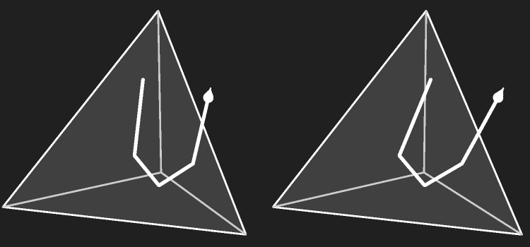
The more inclined the incident light, the smaller is the retroreflected percentage. Part of the light reflected by the prisms at the rear side is reflected back again at the front surface of the foil, reaching the same ( image) or a neighbouring prism (image below). If after one or two reflections part of the light impinges steeply upon a side facet it can get out of the first microprism and enter a neighbouring one, being again refracted and reflected (image).
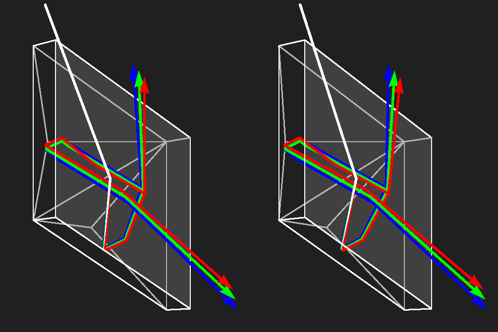
There are many different paths yielding dispersive refraction, thus, in most cases when the sun is shining at such a traffic sign, one can see rainbow colours shimmering at certain angles.
To protect against midsummer heat, the roller blinds of a large window have been nearly closed.
)
)
Standing close to the window and looking down, through the remaining gap the pebbles outside could be seen, and in addition several mirrored images thereof, the light being reflected to and fro between the glass plates. The mirror images of the pebbles were weakly coloured. Strange.
To see more clearly what is happening, a sheet of white paper was placed outside on the ground, and additionally a sheet of black paper was fixed on the outer side of the panes to shield the light coming through the slots of the blinds (left picture below).
)
)
Click on the images for enlargement.
The colours resemble those of thin films, but the panes are not thin and the gap between them is approximately 10 mm. Moreover, there is more than one pattern of interference fringes to be seen. In the lowest mirror image, two superimposed patterns are seen fairly well. (The pictures may be enlarged by clicking on them.)
Clearly, there must be different light paths with almost equal length. The figures below show a selection of possible light paths from the paper to the eye.
) |
) |
) |
) |
) |
| (a) | (b) | (c) | (d) | (e) |
) |
) | |||
| (f) | (g) |
(a): the direct ray which suffers no reflection.
(b): two rays of nearly equal length interfere to yield a colour, but this can hardly be seen, as the angle is almost the same as that of the direct ray. Moreover, the thickness of both glasses must not differ by more than a fraction of the light's wavelength, otherwise, no visible fringes will occur.
(c): Here too interference fringes may occur only if the glasses are equally thick.
(d), and (e): near-equal length light paths producing interference fringes.
(f), (g): light paths with unique length, yielding colourless contributions which desaturate the interference colours.
The interference effects are strongest if at each surface, half of the intensity is reflected and the other half transmitted. This condition is fulfilled approximately if the angle of incidence is sufficiently large, therefore the colours are only seen if one is standing close to the window.
The pictures above have been taken without a polarizing filter. As with each reflection the light becomes more and more s-polarized (the electric field oscillating perpendicular to the plane of incidence), a polfilter may be used to reduce the colourless background, as the ray shown in figure (a) is mainly p-polarized when it reaches the eye. Therefore, with a polfilter one might see the fringes corresponding to figure (b), if there are any.
)
)
Clearly, no fringes are seen in the lowest strip of light. This rules out also the possibility (c), as the thicknesses of the panes differ too much. Thus, the colours of the first mirrored stripe are due to ray paths like (d) and (e).
)
)
Here now, in a narrow region interference fringes are visible in the lowest bright stripe which are due to figure (b) above. Apparently, one of the glass panes is slightly tapered, at one side thinner and at the other side thicker than the other pane, and there is a line where a light path meets exactly equal thicknesses of the two panes. This is where the central white fringe of the pattern is seen.
|
Detail of the left picture above. At the top of the lowest bright region, first the ray (a) is blocked, while the rays (b) are still possible, producing a bright pattern. The colours in the next narrow darker strip are due to multiple reflexions within one of the panes. (Near the right border, part of the transparent adhesive tape is visible. Seemingly, it does not stick to the glass any more and therefore does not disturb the interference pattern.) |
)
|
In shallow water, the light refracted by the wavy surface produces a pattern of bright lines on the ground. Viewed through the wavy surface, the irregular pattern is still more distorted. The lines have colour seams, as the refractive index depends on the wavelength. If the sun is low near the horizon one can see pronounced rainbow colours. Facing the sun when looking at it, the colours are enhanced, while they are reduced when the sun is behind.
)
)
The following picture illustrates how the light rays are refracted and concentrate at bright caustics. (More about caustics may be found on the OPOD pages of Les Cowley.)
)
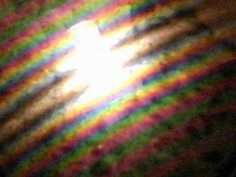

The following observation was also searched for, after having read about it. H.J. Schlichting [1] writes that he saw puzzling colours when looking through an airplane window. Years later he observed the same when looking through an injection-moulded set square (triangle) and found the explanation. In the process of injection moulding, it may happen that the plastics in touch with the mould cools, gets sticky, and is overtaken by the warmer inner layer. When this touches the mould, the process repeats, repeats again and again, eventually resulting in a near to periodic modulation of the optical density.
Presumably, the orientation of the fibrous molecules in the plastics changes periodically leading to periodic changes of the refractivity. This works like a diffraction grating.
) Among about ten set squares I found one which shows this strange phenomenon. |
) A halogen table lamp seen from the side served as light source. |
) The light source seen through the plastic triangle. |
) Holding the triangle at some distance from the (camera's) eye |
) With the naked eye and also under the microscope nothing peculiar is seen at the triangle. |
) Interference colours appearing when the triangle is seen between crossed polarizers indicate that the material is birefringent. Of course, the fine modulation of the refractive index cannot be seen here either. |
Diffraction by feathersA feather held in front of the camera's lens facing the sun. As it is dangerous to look at the sun, for the following experiments artificial light has been used. |
)
|
A small feather from a blackbird (total length 8 cm) illuminated by a lamp with a single white LED shows the coloured spectra in transmitted light very well, if it is held close to the eye.
)
)
The feather's vane represents a composite diffraction grating. This is clearly seen in the photo micrographs below. The branches (barbs) form a regular array and give rise to the central streak of many diffracted, overlapping images of the light source. The barbules on both sides of the barbs are also regularly spaced and account for the brighter colourful diffraction patterns. The barbules are not smooth, but have thin, regularly arranged platelike protrusions which produce some more dim coloured patches.
| In the central part of the feather's vane, the distance between barbs is 1/3 mm, the distance between barbules is about 0.018 mm for the nearly horizontal ones in the picture and somewhat less for the nearly vertical ones. The left picture has been taken with transmitted light only, the right one with additional light from above. The protrusions of the barbules are glittering in the reflected light. |
) |
)
|
The barbules at one side of a barb carry minute hooks and stick to the barbules on the neighbouring side of the next barb.
| A roof-light is shaded by a roller blind which leaves a narrow slit at the side, through which the sun is shining. On the table beneath a coloured pattern is seen. A sheet of paper has been put on the table for the photograph. |
) |
| The pattern changes with the course of the sun. This overview picture was taken some minutes after the upper one. |
) |
| The cause of the coloured stripes is an aluminium rail of the venetian blind mounted at the window frame. The surface of this rail is not smooth but has parallel scratches, traces of machining. These scratches are not regularly spaced and thus the superposition of the waves reflected from the ridges does not result in a regular diffraction pattern but instead in a snarl of colours. |
) |
) |
Pieces of Iceland spar (not only from Iceland) may be found at mineral fairs. These are cropped pieces of large calcite crystals. I was surprised that the clear, colourless pieces in the display of a tradesman showed glinting colours, the origin of which was not obvious. |
) |
With the right viewing angle and illumination, the colours are quite impressive. |
) |
Not all the pieces show these colours, but those which do also show another phenomenon which had already been described by Goethe (J. W. v. Goethe, Farbenlehre, Doppelbilder des rhombischen Kalkspats (1813)). Looking through the spar, in addition to the image looked at, two side images appear. |
As the explanation of the colours and the side images is somewhat involved, a separate section is devoted to the kaleidoscope calcite.
Back to the page “the origins of colour” or home.
Legal Information Data Privacy
![[A]](https://commons.wikimedia.org/wiki/File:Quetelet_close.jpg)
![[B]](https://commons.wikimedia.org/wiki/File:Quetelet_far.jpg)
![[C]](https://commons.wikimedia.org/wiki/File:Quetelet_par.jpg)
)
)
)
)
)
)